
This is the first compact surface-mount board I have designed. It had to be small, tidy and robust enough to live in an engine bay, and because it controls a water/methanol pump it also has to fail safe.
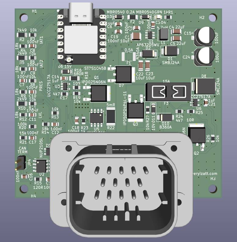
The system it replaces has lived on a bare ESP32-S3 DevKit and an MCP2515 CAN module since the first version of the project. It works, but it is a pile of modules held together with wire, and a pump controller in a hot, vibrating, electrically noisy engine bay should not be one. Revision D puts all of it on one board around a Seeed XIAO ESP32-S3: the pump driver and current sense, the valve output, the sensor inputs, the supply monitoring and CAN, with everything leaving through a single 14-way AMPSEAL connector.
Why I built it
Water/methanol injection is one of the most effective ways to run more boost on pump gas, and the complete kits are expensive. In my car electronics post I compared the AEM water/methanol controller at about $600 to $730 for the controller alone, before the pump, nozzle and plumbing. The parts that do the actual work are cheap: the pump in my setup was about $12, and the nozzle and solenoid about $20. Most of what a kit charges for is the controller in between.
So the goal was a controller made from cheap, universal parts that anyone with a soldering iron could build, and that is not tied to one car or one brand of kit:
- Any diaphragm pump and any normally closed 12 V solenoid. Nothing proprietary, and the pump’s own current tells the board if something is wrong.
- Ordinary sensors. GM-style intake air thermistors, a generic 0.5 to 4.5 V pressure transducer on the nozzle line, a float switch in the tank, and a MAP sensor (GM 2- or 3-bar, or an MPX4250) when the car cannot report manifold pressure.
- Any car. It reads engine data from OBD-II or listens to an aftermarket ECU’s CAN broadcast, so it does not need a particular ECU to work.
- Standard parts on the board. A XIAO ESP32-S3 module, common MOSFETs, a buck converter and passives, rather than anything hard to source.
- No special tuning software. The whole thing is set up from a phone over the board’s own Wi-Fi, and the firmware is open source.
It still has to be safe, so the cheap parts are watched by the guards described below. The point is that a cheap pump and nozzle with a smart controller can be trusted, not that safety is where to cut cost.
The firmware lives in the same repository as the prototype, DIYWaterMethInjection. There is also a live preview of the board’s phone page with a simulated engine, pump and valve behind it, so you can click through every tab without a board.

What is on the board
- Pump driver on a MOSFET, with an INA240 current amplifier across a 5 mΩ shunt, so the firmware sees the pump’s real current every 20 ms.
- Solenoid valve output on its own MOSFET, for a normally closed 12 V valve at the nozzle end of the line. Hardware pulls it shut whenever the ESP32 is unpowered, in reset or still booting.
- Two intake air inputs for ordinary GM-style thermistors. One goes before the nozzle, on either input (the board works out which), and a second after it shows how much cooling the spray actually does.
- A 0.5 to 4.5 V pressure input for a line pressure transducer between the pump and the nozzle, or a MAP sensor when the car cannot provide manifold pressure.
- Tank level switch, wired to ground while there is fluid, so a broken wire reads as a low tank.
- 12 V and sensor supply monitors, and CAN on the ESP32’s own controller, with a jumper for the bus termination.
Everything leaves through the AMPSEAL connector: 12 V twice, ground, the pump and valve, CAN H and L, and the sensors. The CAN termination jumper is only fitted if the board sits at the end of a bus, never on a car’s OBD-II port, which is already terminated.
The design
The silkscreen on the back of the board doubles as the datasheet: the J1 connector pinout and the XIAO’s pin assignments are printed right on it, along with the board’s ratings. Pump driver 10 A maximum, 1 kHz PWM maximum, solenoid output 12 V at 2 A, a nozzle pressure input for a 250 psi transducer or a MAP sensor, a 15 A fuse with a load-dump clamp, and reverse-battery protection.
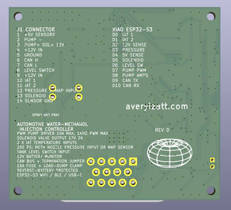
The pin assignments, as printed:
| XIAO pin | Use | XIAO pin | Use |
|---|---|---|---|
| D0 | Intake air 1 | D6 | Tank level switch |
| D1 | Intake air 2 | D7 | Pump PWM |
| D2 | 12 V sense | D8 | Pump current |
| D3 | Pressure | D9 | CAN TX |
| D4 | 5 V sense | D10 | CAN RX |
| D5 | Solenoid |
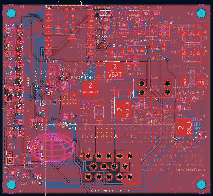
The power side follows the car’s electrical environment rather than a bench supply. Battery power comes in through a 15 A fuse and a 24 V transient suppressor for load dump, then a P-channel MOSFET for reverse-battery protection. A small buck converter makes the logic rail, and the pump is switched low-side by an N-channel MOSFET behind a gate driver, with the 5 mΩ shunt and INA240 reading its current. Every sensor input has its own RC filter, and the CAN lines have ESD protection and the 120 Ω termination jumper.
Two builds from one board
The same hardware runs two firmware builds.
| Build | For | How it gets engine data |
|---|---|---|
WaterMethPCBStandalone |
Any car, no dash | OBD-II requests, an aftermarket ECU’s CAN broadcast, or a MAP sensor on the pressure input |
WaterMethPCBFrogDash |
My Foxbody with FrogDash | The dash’s own CAN protocol, the same one the prototype speaks |
The stand-alone build is the one I would hand to someone else. There is no dash and no laptop: the board makes its own Wi-Fi network, and a phone is the whole interface. The page has tabs for live state, tuning, the nozzle and fluid, the hardware options, engine data, diagnostics and system settings. Four named tune profiles (Street, Track, Race and Winter by default) can be loaded when the engine is not spraying, and every setting can be downloaded as a JSON backup and restored, on that board or another.
For engine data it can ask a car over OBD-II, or just listen to an aftermarket ECU. The ECU list is generated from the profiles in my FrogDash project, each from the maker’s published CAN document: MegaSquirt, Haltech, ECUMaster, MaxxECU, rusEFI, Speeduino, AEM Infinity, FuelTech and Holley. When listening, the board never transmits on that bus.
How it sprays
The pump is an ordinary diaphragm pump, much bigger than the nozzle needs. Run at part duty, it gives the nozzle part pressure and the spray turns coarse. So the board runs it full on or full off in timed pulses and sets the flow by how long it runs in each cycle.
- A pulse is at least 500 ms on or not at all, and rests at least 500 ms or stays on.
- Each run starts with a soft start, 5% duty up to full over 0.4 s.
- There is no injection without fresh engine speed above a minimum, and a dose limit holds the fluid to a set share of estimated fuel flow.
- Optional early start and hot-air triggers can add cooling, but only inside every rule above.
The nozzle’s flow matters for the dose limit, and the label is not a reliable source. The nozzle on the prototype is sold as 60 ml/min and measured 160 at my pump’s pressure. The board has a measure-it test for that: catch a test spray in a cup, weigh it, enter the grams and the page works out the flow. With a line pressure transducer fitted it also records the pressure during the test, so it can scale the flow with the square root of pressure afterwards and keep a running count of fluid used since the last fill.
Making it hard to hurt the car
The part of this I spent the most time on is the safety logic, because a water/meth pump that sticks on is a real problem. The guards run independently of the logic that is supposed to get things right.
| Guard | Watches | Then |
|---|---|---|
| Short circuit | One reading over 25 A | Pump off at once, latched |
| Over-current | Over the limit for 0.3 s | Pump off, latched |
| Pump not connected | Under 0.3 A after 0.6 s running | Pump off, latched |
| Line pressure | Too low at full drive, or too high (a blocked nozzle) | Pump off, latched |
| 12 V supply | Under 10.5 V or over 16.5 V | Held, released when it recovers |
| Pump keeper | The control loop refreshing the pump, checked from the other core | Pump and valve off after 0.25 s |
| Output read-back | The pump PWM and the valve pin against what was set | Off, latched |
| Spray budget | How long the pump has really been on, counted from the output | Off, latched |
| Task watchdog | Both cores | Restart, with the crash hook switching pump and valve off first from registers |
A pump switch that fails shorted still cannot spray, because the valve stays shut. After an unexpected reset the board comes back armed if it was armed, reports the restart and sends a black box of the last ten seconds. Repeated crashes hold injection off for a while, longer each time.
Faults are kept the way a car’s ECU keeps them: trouble codes with a count, first and last occurrence and a freeze frame of boost, engine speed, pump duty and current, line pressure, supply voltage and air temperature at the time. They show on the Diagnostics tab and over USB serial.
Testing it
The logic that decides what the pump does is plain C++ with no Arduino calls, so it runs on a PC. The repository has twelve test suites covering the pulse timing, the dose limit, the soft start, the input conversions, reset recovery, the black box, the LED, the knock filters and the controller’s failsafes, and CI runs them on every push. A second check rebuilds the phone-page preview and fails if it is out of date.
Where it stands
Rev D is designed and the firmware is written and tested on a PC, but it has not run on a real board yet. The first power-up is a short checklist: USB only to read the self-test, then 12 V with no pump (a test spray should trip “pump not connected” after 0.6 s, which proves the current sense), then the pump and valve with the nozzle in a cup. Only then does it go near the car. I will write that up once the hardware has been through it.
The schematic and layout live in a private KiCad project, so they are not in the repository. The firmware repository has the wiring table, the settings reference, the CAN protocol and the bench procedure.