This is the next major step in my programmable taillight project for the 1989 Fox Body Mustang. The controller has moved beyond the original ESP32-S3 DevKit wiring and now has a dedicated firmware target for my custom PCB. The board brings the lighting outputs, isolated factory-signal inputs, CAN interface, and spare expansion I/O into one purpose-built controller while keeping the same 760-pixel taillight system.
What Changed in This Revision
The original version proved the lighting architecture on an ESP32-S3 development board with external optocoupler and MCP2515 modules. This update keeps that software architecture but adds a separate esp32-s3-pcb PlatformIO environment for the custom board. That build is now the default, so the same codebase can target either the earlier DevKit setup or the new PCB without maintaining two different firmware projects.
- Dedicated custom-PCB pin map selected at compile time
- Three LED data outputs: driver, passenger, and one spare
- Six optocoupled 12V input channels, including one spare input
- Onboard MCP2515 CAN interface operating at 500 kbit/s
- Two additional spare GPIO connections for future expansion
- Updated FastLED output timing for reliable dual-panel rendering
Taillight Panel Architecture
Each side still contains 380 WS2812B LEDs, for 760 addressable pixels total. A side is divided into three serpentine matrices: a 21 × 5 top strip, a 21 × 5 bottom strip, and a 17 × 10 main section. The top strip sits behind a clear section of the lens, while the lower strip and main panel sit behind red diffusers. The firmware applies diffuser-aware color filtering automatically, so an animation can be written in normal RGB values and the panel layer handles the physical lens restrictions.
| Section per side | Matrix | LEDs | Lens behavior |
|---|---|---|---|
| Top strip | 21 × 5 | 105 | Clear / full color |
| Bottom strip | 21 × 5 | 105 | Red-filtered |
| Main panel | 17 × 10 | 170 | Red-filtered |
| Total | Per side | 380 | 760 across both sides |
Custom PCB Pinout
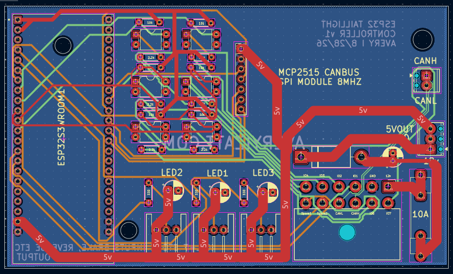
The PCB build maps the driver taillight to GPIO 4 and the passenger taillight to GPIO 6. GPIO 5 remains available as a third LED data output. The isolated vehicle inputs use shared brake, running-light, and reverse signals, with independent driver- and passenger-side turn inputs. That matches the way the factory signals need to be resolved while preserving a spare optocoupler channel.
| PCB connection | GPIO | Function |
|---|---|---|
| LEDDATA1 | 4 | Driver taillight |
| LEDDATA3 | 6 | Passenger taillight |
| LEDDATA2 | 5 | Spare LED output |
| OPTOGPIO1 | 7 | Brake input |
| OPTOGPIO2 | 15 | Running-light input |
| OPTOGPIO3 / 4 | 16 / 17 | Driver / passenger turn |
| OPTOGPIO5 | 18 | Reverse input |
| OPTOGPIO6 | 8 | Spare isolated input |
| CAN CS / MISO / MOSI / SCK | 38 / 37 / 40 / 41 | MCP2515 SPI bus |
| SPARE1 / SPARE2 | 46 / 9 | Future expansion |
The spare pins are intentionally left unconfigured in normal firmware. That prevents attached future hardware from being driven accidentally before its behavior is defined.
CAN Bus and Fault-Tolerant Operation
The onboard MCP2515 connects the taillight controller to the rest of the vehicle electronics network at 500 kbit/s. The existing protocol remains compatible with my other modules: ID 0x100 broadcasts taillight state every 100 ms, 0x101 receives commands, and 0x102 reports faults.
On this PCB revision the original CAN interrupt trace is isolated, so the controller polls the MCP2515 instead. The runtime CAN path is designed to stay non-blocking: one-shot transmission prevents endless retries when no node acknowledges a frame, failed transmissions back off, and the lighting logic continues even if the CAN network is disconnected. That separation is important because a communications fault must never stop the basic brake, turn, running, or reverse functions.
Lighting Safety Comes First
The visual effects are the fun part, but the firmware treats the controller as an automotive safety system first. Physical brake and reverse inputs always override CAN-requested animations. Each side resolves its state independently, which allows the controller to handle combinations such as brake plus turn without losing the required signal on either side.
- Hardware watchdog: monitors both the input task and rendering loop with a three-second timeout.
- Dual-core input handling: factory signals are sampled independently from LED rendering and shared through atomic snapshots.
- Crank holdoff: keeps the LEDs blank for 1.5 seconds after boot so a voltage sag during engine cranking produces a clean restart.
- Thermal protection: begins reducing brightness at 75°C and clamps to a safe minimum above 85°C instead of switching the lamps completely off.
- Bench self-test: holding the driver running-light input during power-up checks segments, pixels, colors, and every lighting state.
Reliable LED Output
Driving two long WS2812B chains while also servicing CAN and Wi-Fi requires predictable timing. This revision pins FastLED 3.10.3 and uses the synchronous ESP32 RMT driver with two memory blocks. Physical LED updates are limited to 50 frames per second. These changes keep output stable while the controller processes network traffic, the settings page, thermal monitoring, and vehicle inputs.
Web Configuration and New Effects
The ESP32 can create its own Wi-Fi access point or join an existing network and serve a built-in configuration page. From a phone or laptop I can adjust brightness, running-light intensity, signal colors, animation selection, frame timing, startup behavior, show mode, and custom scrolling text. Settings are stored in NVS, and live preview controls make it possible to test a state without applying 12V to every physical input.
The latest animation set also takes better advantage of the matrix-shaped panels. New road-use options include Contour Glide and Fox Louvers for running lights, Edge Lock for braking, and Arrowhead Sweep or Three-Bar Relay for turn signals. Show mode adds effects such as Afterburner, Tunnel Grid, and Apex Weave. Passenger-side geometry is mirrored in the panel layer, so directional effects remain symmetrical without maintaining separate artwork for each lamp.
Where the Project Stands
This update brings the custom PCB and the full taillight firmware together. The controller now has a clean hardware-specific build, isolated factory inputs, dependable dual-panel output, CAN telemetry and commands, a browser-based setup interface, and safety behavior that remains in control even when a higher-level feature fails.
The video above shows the updated system operating on the new controller. The next stage is continued vehicle-side validation: checking the harness under real voltage conditions, confirming behavior during cranking, and testing CAN traffic with the other modules installed in the car.