
As part of my engineering journey at Colorado Mesa University, I had the opportunity to participate in the Colorado Space Grant Consortium (COSGC) robotic rover challenge. COSGC is a NASA-sponsored undergraduate research program that allows students to gain hands-on experience designing real-world aerospace systems.
Our team was tasked with designing, building, and testing a planetary rover prototype capable of navigating variable terrain, detecting obstacles, and collecting basic environmental data. The project culminates in a statewide competition on April 12th, held in the Great Sand Dunes National Park, where our rover will be evaluated on performance, robustness, and autonomy.
COSGC Program Overview & Design Reviews
The COSGC program isn’t just a student showcase—it mirrors real NASA engineering workflows. That includes multiple formal design reviews, held with COSGC program directors and engineering professors from the University of Colorado Boulder. Each review challenged us to justify our engineering decisions, present data and documentation, and respond to constructive criticism in a professional format.
During our Initial Design Review (IDR), we proposed a rocker-bogie suspension system inspired by NASA’s own Martian rovers. Our presentation included 3D CAD renders, mechanical simulations, and wiring schematics.
Despite the ambition, the CU Boulder faculty raised valid concerns:
- The design was mechanically complex
- It exceeded the scope of our timeline and material constraints
- It was prone to failure without precision-machined parts
Their advice: simplify, modularize, and focus on core function over form.
That feedback fundamentally shaped our approach. We went back to the drawing board and committed to building something reliable, testable, and modular.
Mechanical Architecture & Chassis Fabrication
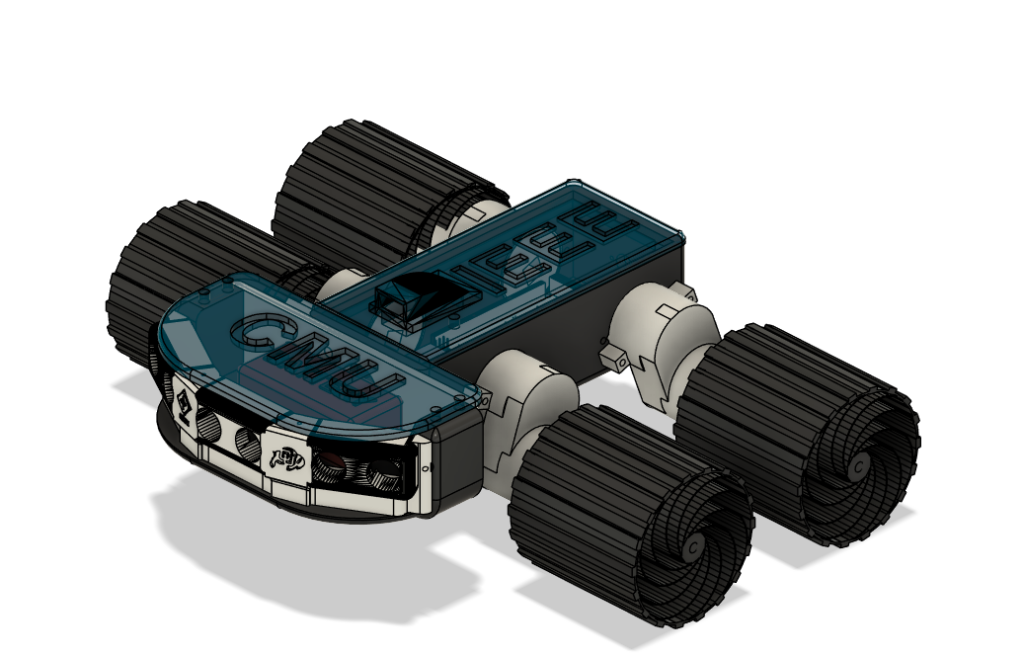
We pivoted to a skid-steer rover platform, opting for simplicity, robustness, and controllability. This involved four independently driven wheels, allowing the rover to turn by varying motor speeds on each side—similar to how a tank steers.
I took the lead on mechanical design and fabrication:
- Designed the entire chassis in CAD, using Fusion 360
- Built with custom 3D-printed components, reinforced with inserts for field service
- Integrated quick-swap side panels for access to internal wiring and electronics
- Designed mounts for sensors, drivers, battery, and power regulation components
The chassis is compact, rugged, and field-serviceable. It was designed to handle minor collisions, uneven terrain, and dusty environments while still being modular enough for in-field repairs.
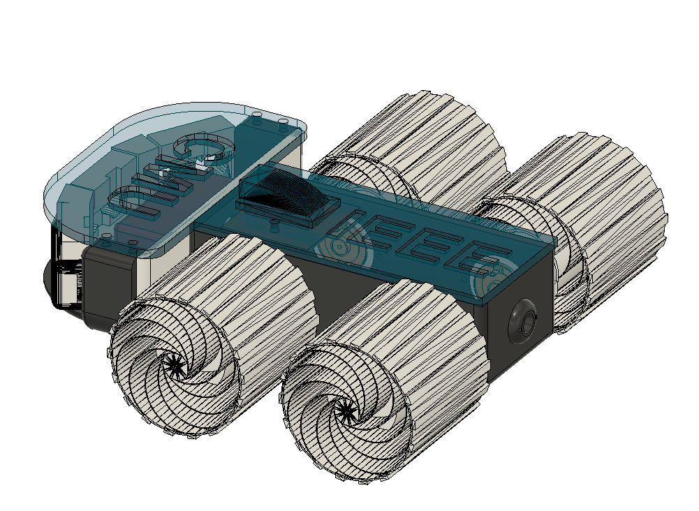
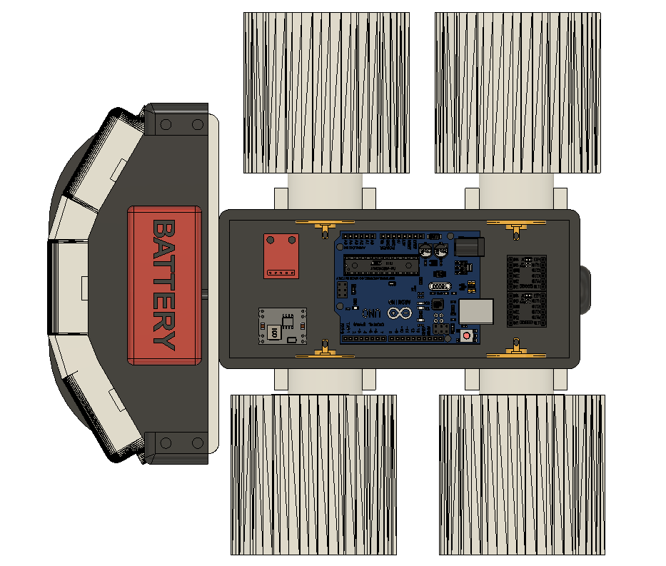
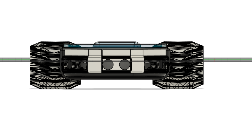
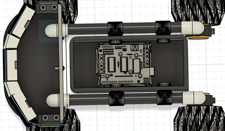
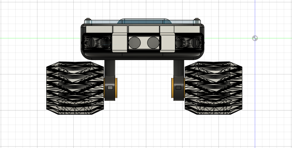
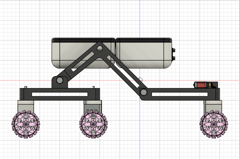
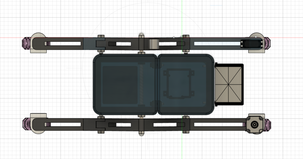
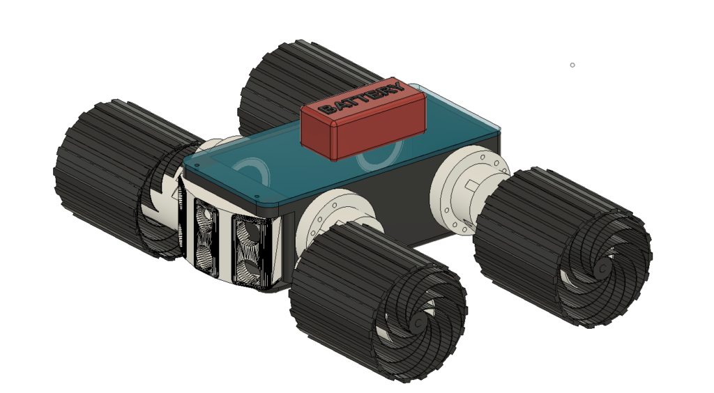
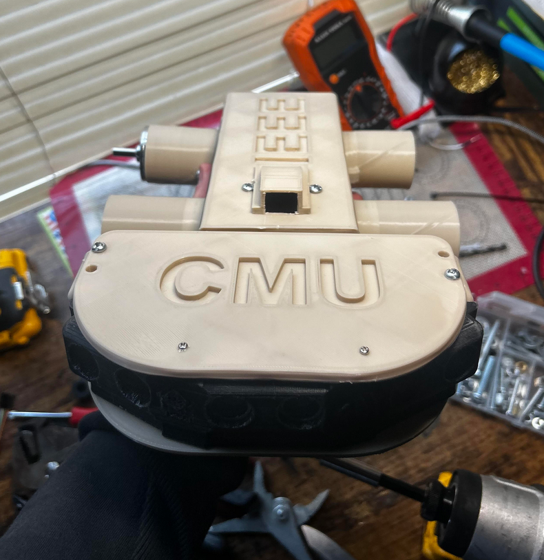
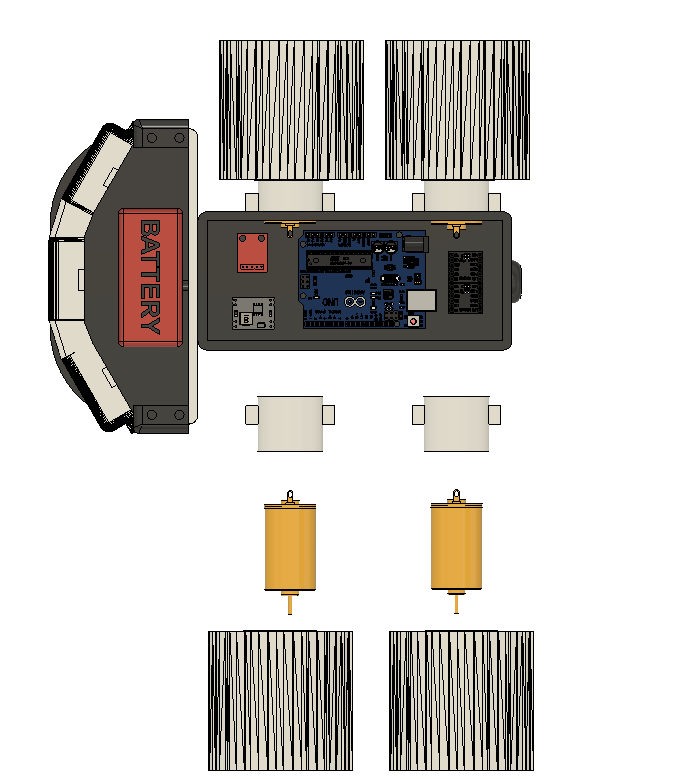
Explore the print files
These are four of the actual Fusion 360 exports from the final mini-rover design. They show how the body, sensor face and spiral wheel were split into printable, replaceable parts. Tap one to load it in the interactive viewer; the original .3mf is also available below each model.
Electrical System & Power Distribution
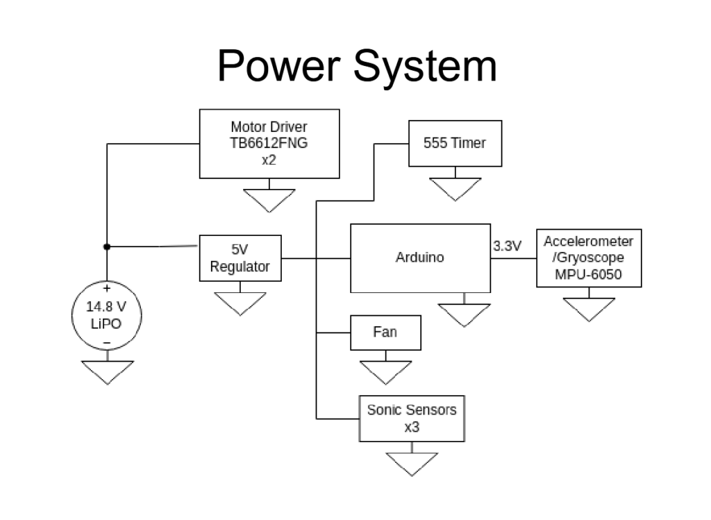
Our power system centered on a 14.8V LiPo battery, chosen for its energy density and current output. From there, the system branches into separate regulated paths:
- 5V Rail (via Buck Converter): powers Arduino, ultrasonic sensors, 555 timer circuit, and cooling fan
- Motor Path: directly feeds two TB6612FNG motor drivers to control four DC motors
- 3.3V Line: powered through onboard regulation on the Arduino, used for I2C sensors like the MPU-6050
A key focus was power isolation and stability. All ground paths were linked via a star-grounding scheme, and capacitors were placed to buffer the regulators against voltage spikes.
Sensor Suite & Timing Logic
The rover’s autonomous capabilities rely on:
- Three Ultrasonic Sensors (front-facing and angled sides)
- MPU-6050 Accelerometer/Gyroscope for pitch/roll detection
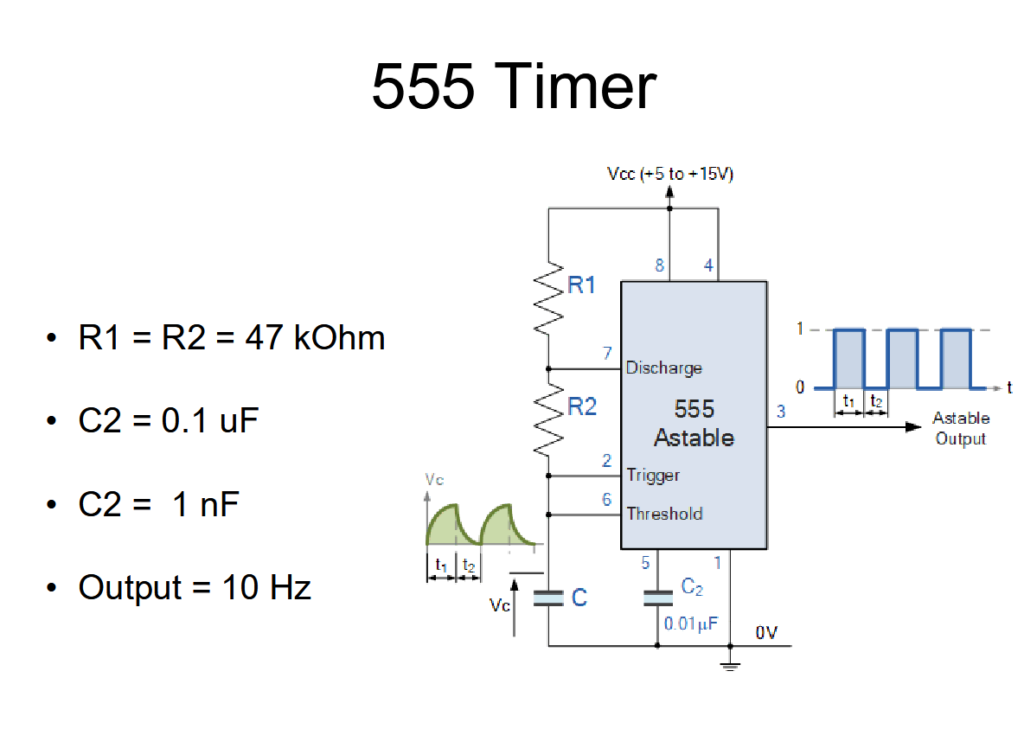
- Custom 555 Timer Circuit generating consistent trigger pulses for the sensors
The 555 timer was configured in astable mode to produce a 10 Hz output signal. This ensured precise timing for ultrasonic trigger events, avoiding signal overlap or missed echoes.
555 Timer Circuit:
Embedded Code Architecture & Task Scheduling
The software architecture was custom-built around a lightweight task manager written in C++. It breaks system behavior into manageable tasks:
task_create(): Registers new taskstask_tick(): Called from the main loop, checks for due taskstask_int(): Watchdog function to prevent system hangs- Callback functions handle sensor reads, motor control, and error handling
Each task runs independently, ensuring the system remains responsive even under load or in failure conditions.
Software Diagram:
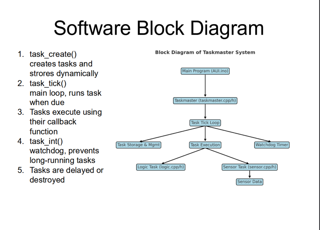
This modular software approach made it easy to debug, tune, and expand behavior without affecting the main control loop.
Real-World Testing & Performance Tuning
We conducted testing in a variety of conditions:
- Mulch beds for traction loss simulation
- Gravel for bump and noise testing
- Asphalt for precise turning calibration
- Dirt hills to simulate the dunes
During testing, we monitored:
- Motor balancing (one side drifting? Tune PWM)
- Sensor blind spots (adjust mounting angles)
- Temperature inside the chassis (verify fan effectiveness)
We ran real-time data logging through serial output and tested how the rover responded to obstacles, slopes, and fast motor reversals. We were able to change ultrasonic sensors and remount boards in under 2 minutes due to the modular design.
🏁 Final Prep for the Dunes
As of now, the rover is fully assembled, tested, and tuned for the Great Sand Dunes challenge on April 12th. The system is robust, modular, and engineered to be repairable in the field. Our documentation is ready, and our codebase is version-controlled and backed up.
This project pushed us to operate like real engineers. From design reviews with CU Boulder professors to rigorous hardware testing in real terrain, we developed:
- Technical presentation skills
- System-level thinking
- Rapid prototyping and iteration workflows
We’re proud to represent Colorado Mesa University in a statewide NASA-backed competition—and we’re even prouder of what we built.