
COSGC-ROBOT is the repository behind our Colorado Space Grant Consortium competition robots. It has been in development since February 2025 and holds every platform we’ve built, from Arduino-based first versions to the current tracked rovers. This page is about the current one: a tracked rover meant for sand pits, inclines and obstacle fields, with two software stacks, ESP32 firmware that drives it on its own and a Raspberry Pi 4 vision stack.
The ESP32 firmware

The firmware is C++ on PlatformIO for an ESP32 WROOM-32. It reads two HC-SR04 ultrasonic sensors, an MPU-6050 IMU and two hall-effect wheel encoders, and drives two DRV8871 motor drivers with 20 kHz PWM. A servo on a 330 Hz signal moves the self-righting arm. Every motor command, whatever its source, goes through the same safety stack before it reaches a driver.
Two pin-level lessons are worth writing down:
- GPIO 25 and 26 share silicon with the ESP32’s two DAC channels. If the DACs aren’t explicitly disabled at boot, they silently override the PWM output on those pins. The firmware disables both before attaching the LEDC PWM channels.
- GPIO 12 sets the flash voltage at boot, so it is never used as an output.
Six modes, one button

A short press of the mode button cycles through the modes and the RGB LED changes colour to say which one is active, flashing three times to confirm. A long press in RC mode starts pairing for the Xbox controller.
- UART: binary motor commands from a host computer. Packets are framed
[0xFF] [type] [length] [data…] [checksum] [0xFE]with an XOR checksum that is validated before anything is acted on. - RC: an Xbox One or Series controller over Bluetooth LE using Bluepad32. The left stick drives and the right stick steers with skid-steer mixing (
left = drive + steer,right = drive − steer). The triggers move the self-righting arm. Bluetooth is only running in this mode and is shut down fully when leaving it, which frees about 60 KB for the Wi-Fi access point. If no input arrives for 500 ms, the motors stop. - Autonomous: the main competition mode, described below.
- Simple auto: a lightweight mode that uses only the front ultrasonic distance. It speeds up and slows down with distance (100 cm and 50 cm thresholds), turns at 20 to 50 cm and reverses below 20 cm, and keeps the IMU-based terrain features.
- Wall follow: a left-hand-rule follower with a PID loop (Kp 4.5, Kd 1.8, Ki 0.04) holding 28 cm from the wall, with integral windup limiting. It turns left when it loses the wall (over 100 cm), turns right when blocked, and slows when something is close ahead.
- Pre-map: the same navigation as Autonomous, but the occupancy map is drawn in advance in the web UI and uploaded before the run.
Autonomous navigation

Cruise. The rover follows waypoints from a wavefront path planner on a 10 × 10 occupancy grid, steering proportionally to heading error. After half a second in cruise the IMU-integrated heading is locked and a heading-hold correction keeps it straight. Dead-reckoning from the wheel encoders biases it away from its start point so it doesn’t circle back.
Avoid. Triggered when the forward distance drops below 35 cm (15 cm is a critical stop with a longer back-up). It backs up for 400 ms, turns toward whichever ultrasonic side is more open (alternating if they are equal, so it can’t loop), then drives forward briefly to verify clearance. It keeps a memory of the last eight obstacle headings and penalises repeating a direction. If it picks the same direction four times in a row, it escalates to recovery. If it turns more than six times in ten seconds, a 2.5-second full-power burst breaks the loop.
Recover. A scripted “rock and roll”: rock back and forth, approach diagonally, then a two-second full reverse. Afterwards an adaptive ramp slows the PWM change rate for three seconds so the tracks don’t dig into loose sand.
Hazard. The IMU watches for terrain the ultrasonics can’t see: pitch above 15° for half a second is a hill, below −15° is a pit or drop-off (back up 600 ms), a sudden distance jump of more than 80 cm marks a pit edge, accelZ < −0.5 g means the rover is upside down and |roll| > 45° means it’s on its side. Either flip triggers the self-righting arm. Gentle terrain (under 20° pitch or about 15 cm high) is crossed at full speed. Major terrain triggers a back-up and a re-route, and cells are marked in the map as hills or pits.
Traction control. When the encoders say the wheels are spinning (above 5 cm/s) but the IMU shows the body isn’t moving, power is cut to a lower level for 400 ms to let the tracks regain grip. After four failed cuts it escalates to avoidance, with a five-second cooldown. If either the IMU or an encoder has been flagged as faulty, traction control is bypassed rather than trusting bad data.
Sensing details that mattered
- Two angled ultrasonics, one picture. The sensors point about 15° left and right and fire 500 µs apart to avoid crosstalk. Readings go through a 70/30 exponential filter, and simple trigonometry turns the two distances into a centre distance, a wall angle, a gap width and the nearest obstacle’s position. A sensor frozen at one value for over three seconds is flagged as faulty.
- IMU calibration and partial reads. The MPU-6050 calibrates at startup (50 settling samples discarded, 200 averaged, with the Z axis offset by 1 g, so the rover must be flat and still). If an I²C read times out mid-frame, the incomplete 14 bytes are discarded instead of zero-padded, because a zero
accelZwould look exactly like being upside down.
Nine layers of motor protection
Every motor command passes through these, and they run every loop before any mode handler:
| Layer | What it does |
|---|---|
| Current-based PWM cap | The maximum PWM is computed at boot from the driver’s safe current, battery voltage and motor resistance: 3.5 A gives about 87% duty |
| Slew-rate limiter | PWM changes by at most 55 (up) or 50 (down) per 10 ms |
| Direction dead-time | 15 ms of coast when reversing, to prevent shoot-through in the H-bridge |
| Minimum speed boost | Non-zero commands below 60 are raised to 60 to overcome static friction |
| Thermal monitoring | ESP32 temperature checked every 2 s: above 65 °C throttle to 50%, above 75 °C emergency stop, resume below 55 °C |
| Duty-cycle limiter | After 20 s at full speed, throttle to 50% for 3 s |
| Motor watchdog | No motor command for 500 ms stops the motors |
| Startup delay | Motors locked for 1 s after boot while the power rails settle |
| Emergency stop | Critical faults latch until reboot |
Motor B is also trimmed to 95% to cancel a small drift to the right.
Dashboard and pre-mapping
The rover runs its own Wi-Fi access point (TankBot-AP) with a captive-portal DNS, so a phone opens the dashboard automatically. The dashboard polls a JSON status endpoint every 500 ms and shows odometry, encoder speeds, motor commands, both ultrasonic readings, planner state, IMU data, uptime, free heap and the live occupancy map, colour-coded by cell type.
A map editor lets me paint walls, hazards, pits and hills on the 10 × 10 grid, set the start position and upload it to the rover with one HTTP POST. In Pre-map mode the rover plans around what I drew and keeps refining the map from its own sensors during the run.
The Raspberry Pi vision stack

The other platform is a Pi 4 with a camera and a dual H-bridge driver, written in Python with OpenCV and TFLite. It is split into layers so each can be tested and tuned on its own: perception (obstacle detection with a TFLite SSD model and a contour fallback, boundary detection, and a texture-based rockiness score tuned for bright sandy scenes), decision (turns perception into a short command like FORWARD, TURN_LEFT or STOP_REVERSE), motor control with safety checks and a keepalive watchdog that stops the motors if the network drops, an overlay that draws debug information on the video, and a Flask dashboard with RC override (including an Xbox controller through the browser) and live tuning of thresholds while the rover runs.
There are also early hooks for SLAM, a moving-obstacle tracker built on a Kalman filter with Hungarian assignment, and an occupancy grid with A* path planning.
3D-printed parts
The rover’s drivetrain and housings are modelled in CAD and printed. These are the actual print files, so you can spin them around, flip on the wireframe to see the mesh, or download them.
Team NULLPTR and the design review
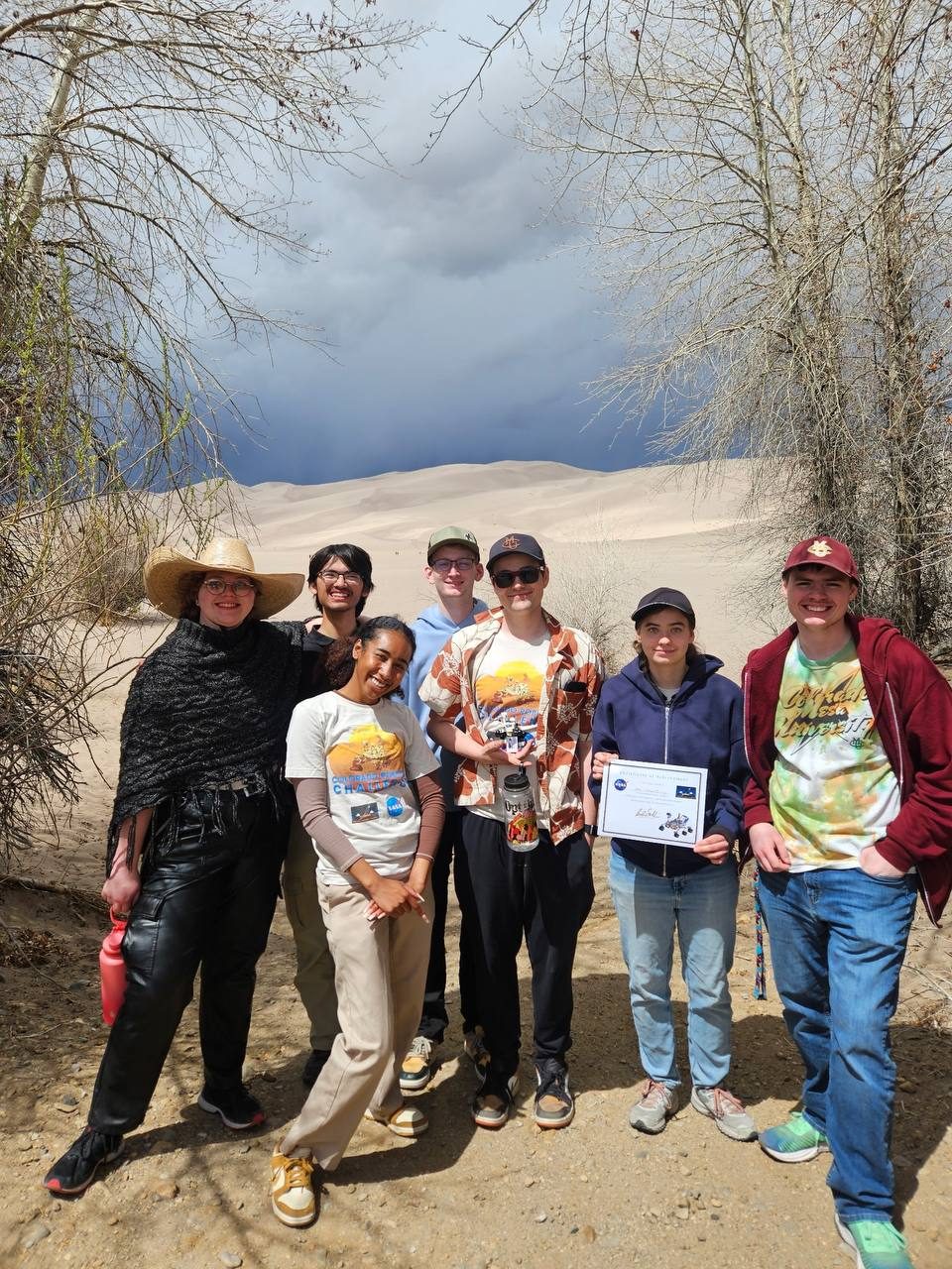
In fall 2025 our team of eight, NULLPTR, presented a Critical Design Review. The goal was a small rover that can cross a rugged, sandy, desert-like course on its own and avoid obstacles. The requirements we set were:
- stay under $500 and 5 kg
- be as robust and fail-resistant as possible
- drive autonomously over sand and small obstacles
The plan was a Raspberry Pi 5 for the brain, a stereo camera plus ultrasonic sensors for obstacle detection, 12 V DC motors with skid steering, a 14.8 V LiPo battery, and a 3D-printed track-style chassis. We also wanted the project to give the new club an identity and a reason to visit the Great Sand Dunes.
What the final design review documented
By the April 3, 2026 Critical Design Review, the actual rover had converged on the simpler ESP32 architecture described above. It weighed about 1.8 kg and measured 17.8 cm wide × 33.0 cm long × 15.2 cm high, or 40.6 cm to the top of the self-righting arm. The arm used a 35 kg·cm metal-gear servo and a high mounting point to create enough righting moment on uneven ground.
The design review recorded the progression from isolated subsystem checks to indoor autonomous runs: ultrasonic calibration, PWM response and regulator outputs passed individually; the motor drivers, sonar, IMU and recovery servo ran together without a reset or brownout; and obstacle avoidance was repeatable indoors. The final week was reserved for uneven-ground testing, battery-margin checks, locking the wiring and rehearsing the competition procedure. The next hardware step was a custom four-layer PCB to reduce weight and wiring while improving reliability and expandability.
Competition day, April 2026
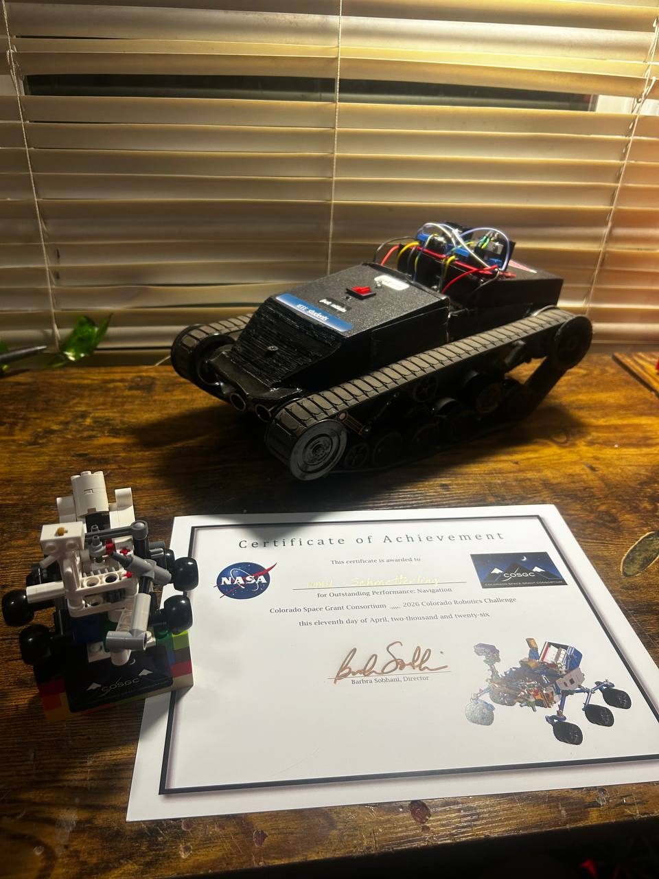
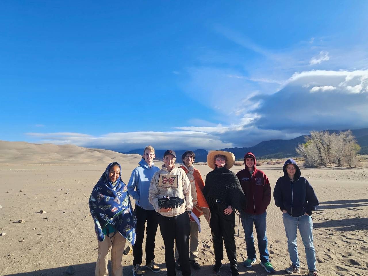
The 2026 Colorado Robotics Challenge ran in the sand dunes. It came with a NASA and Colorado Space Grant Consortium Certificate of Achievement for Outstanding Performance: Navigation, dated April 11, 2026.
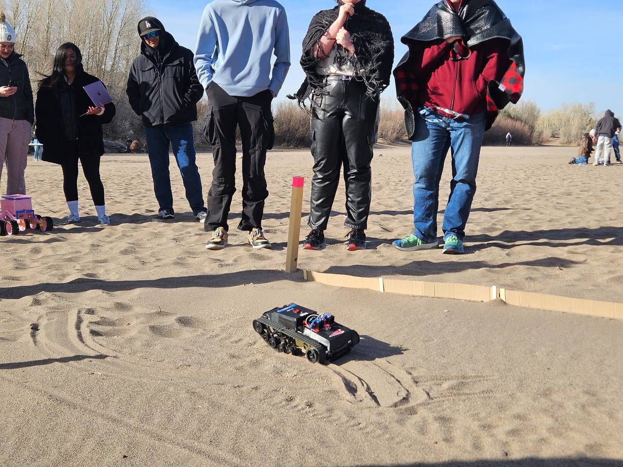
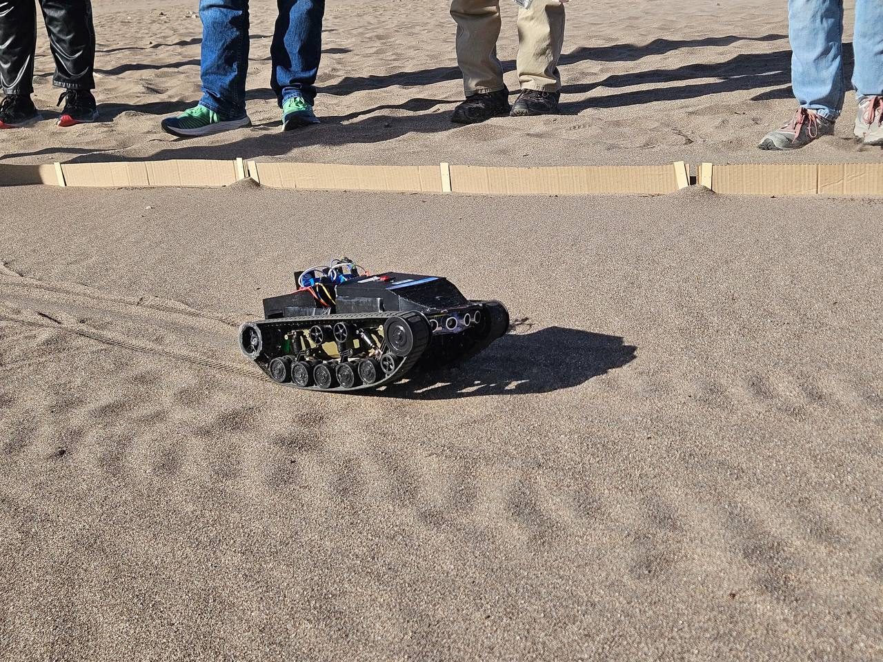
The course was a lane marked out in the sand with cardboard walls. The rover had to cross it on its own, using the ultrasonic sensors and IMU described above, while the teams and spectators watched from the edge.
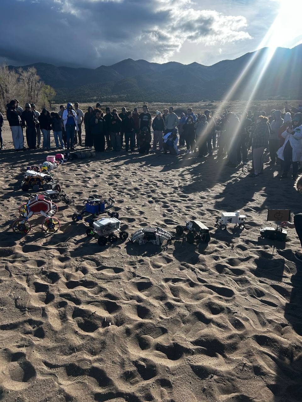
Every team lined its robot up in the sand at the start. Ours was one of a very mixed field, from wheeled rovers to a pink box-bodied one.
Video
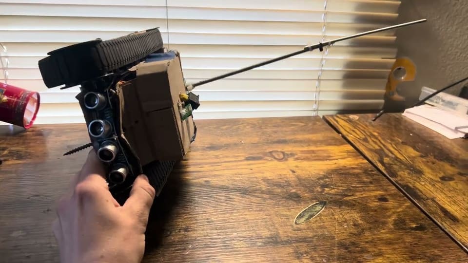 COSGC Robot Competition: rover self-righting armyoutube.com
The source for everything above is on GitHub, including the earlier Arduino Mega and Mini robots.