Designing a Distributed Embedded Vehicle Architecture Using CAN Bus
When most people think about modifying a vehicle with electronics, they imagine adding a few sensors, an Arduino, or perhaps a digital dashboard. Modern vehicles, however, are built very differently. Rather than relying on a single computer, today’s automobiles contain dozens of Electronic Control Units (ECUs), each responsible for a dedicated subsystem. These independent processors communicate continuously over high speed Controller Area Networks (CAN), allowing every module to share information while remaining largely autonomous.
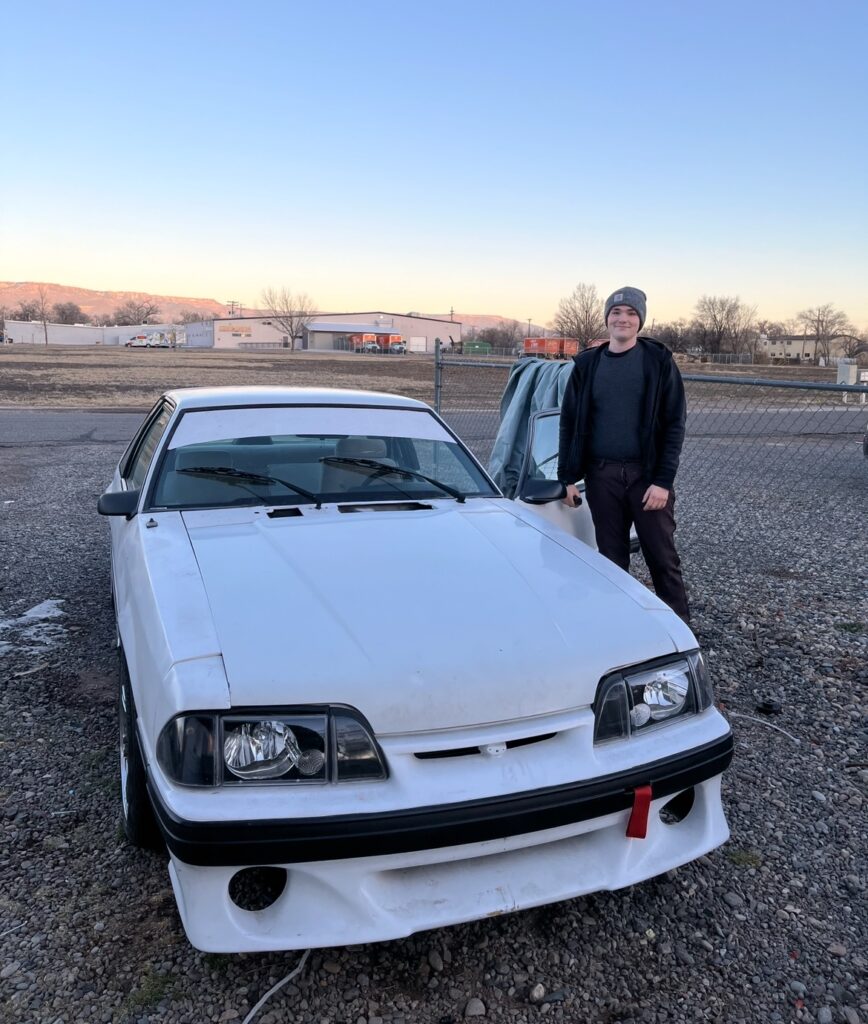
This project explores those same engineering principles by transforming my 1989 Ford Mustang into a distributed embedded system built around multiple ESP32 based controllers connected through a custom CAN bus network.
Instead of creating one large controller responsible for every sensor, display, light, and actuator, each subsystem is implemented as its own intelligent processing node. Every controller is physically located near the hardware it manages, reducing wiring complexity while improving modularity, reliability, and long term maintainability.
The project began as a simple led project controller but has steadily evolved into a complete vehicle electronics platform. Today the network manages engine monitoring, interior systems, telemetry, lighting, user interfaces, diagnostics, and data acquisition while remaining expandable for future modules.
The overall objective is not simply to add new features to an older vehicle. Rather, the goal is to design an architecture that mirrors many of the software and hardware design philosophies found in modern automotive electronics while remaining completely open source, fully customizable, and built entirely from commercially available hardware.
Design Philosophy
Large embedded projects naturally become more difficult to maintain as additional hardware and software are introduced. Every new sensor, output, or feature increases software complexity, wiring requirements, debugging time, and the potential for failures.
Rather than accepting this complexity, the system is intentionally designed around a modular architecture. Each processor performs one primary role exceptionally well.
Instead of routing dozens of analog sensors across the length of the vehicle into one controller, intelligent nodes are positioned where they are most useful. Sensor processing occurs locally, decisions are made locally whenever possible, and only meaningful information is transmitted across the CAN network.
This philosophy provides several important advantages.
First, wiring is dramatically simplified. Instead of running individual signal wires throughout the vehicle, each module requires only power and two CAN wires for communication. This not only reduces wiring weight but also improves reliability and simplifies future expansion.
Second, software becomes significantly easier to maintain. Each firmware project remains focused on one subsystem, allowing new features to be implemented without risking unrelated portions of the vehicle.
Finally, every subsystem becomes replaceable. Additional processors can be added to the network with minimal changes to existing hardware, making the vehicle an expandable embedded platform rather than a collection of individual electronics projects.
System Architecture
The vehicle currently consists of several intelligent processing nodes connected by a common CAN network.
At the center of the user experience is an ESP32-S3 dashboard controller responsible for the graphical interface and user interaction. Mounted within the cabin, this processor manages a capacitive touchscreen display, GPS functionality, Bluetooth communication, race telemetry visualization, onboard data logging controls, diagnostics, configuration menus, and interior ambient lighting.
Unlike a traditional dashboard, the display itself performs very little direct hardware control. Instead, it functions as the primary human machine interface, issuing CAN commands to dedicated controllers located throughout the vehicle. This separation allows user interface development to remain independent from real time control software while significantly improving maintainability.
Within the engine bay, an Arduino Nano ESP32 acts as the dedicated engine subsystem controller. This processor continuously monitors engine related sensors while managing the custom progressive water methanol injection system. Oil pressure, fuel pressure, intake air temperature, knock sensing, and additional safety inputs are processed locally before being shared across the CAN network.
By locating this controller close to the engine, analog sensor wiring remains short, electrical noise is reduced, and sensor processing can occur independently of the dashboard. Safety critical logic such as water methanol failsafes can continue operating regardless of what is displayed on the touchscreen.
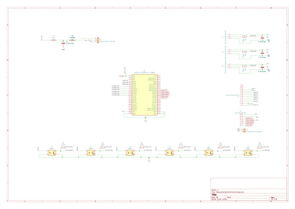
At the rear of the vehicle, a dedicated ESP32 controls all rear lighting functions. Brake lights, reverse lights, turn signals, sequential animations, startup sequences, and future lighting effects are handled entirely within this module. The dashboard simply issues high level commands while the lighting controller executes animations and reports status information back across the network.
The final major participant within the CAN network is the MicroSquirt engine management system. Rather than replacing the ECU, the embedded controllers complement it by consuming engine telemetry, displaying live information, logging data, and integrating additional functionality beyond the scope of traditional engine management.
Collectively these processors form a distributed computing platform where every module performs a specialized task while contributing to a unified vehicle control system.
Human Machine Interface
One of the most visible components of the project is the custom touchscreen dashboard developed using LVGL.
The interface serves as the primary interaction point between the driver and every embedded subsystem. Rather than functioning as a simple digital gauge cluster, the dashboard behaves more like a modern automotive infotainment system, providing access to configuration, diagnostics, telemetry, sensor visualization, and subsystem control.
The interface currently includes live engine monitoring, water methanol system controls, GPS navigation information, race telemetry, Bluetooth connectivity, onboard data logging management, interior lighting customization, and comprehensive diagnostic pages displaying live sensor information from throughout the vehicle.
Because every subsystem communicates through CAN, new pages and features can be developed without modifying existing hardware. Additional sensors immediately become available to the interface simply by publishing new CAN messages.
Race Telemetry and Data Acquisition
A major objective of the platform is providing meaningful data rather than simply displaying gauges.
The vehicle continuously collects operating information from multiple embedded controllers while generating synchronized telemetry that can be reviewed after a drive or performance event. Engine parameters, pressure sensors, knock activity, GPS information, water methanol operation, and additional vehicle data can be recorded simultaneously.
This architecture transforms the vehicle into a mobile data acquisition platform capable of capturing significantly more information than traditional standalone aftermarket gauges.
Rather than requiring multiple independent logging devices, every subsystem contributes data to a common telemetry framework that can later be analyzed for performance tuning, diagnostics, or reliability improvements.
CAN Bus as the System Backbone
Controller Area Network serves as the communication backbone connecting every processor within the vehicle.
Instead of transmitting raw electrical signals between modules, each controller publishes structured messages describing sensor values, commands, status information, and fault conditions. Every processor subscribes only to the information it requires, greatly reducing software coupling while maintaining high system flexibility.
This publish subscribe architecture allows entirely new controllers to be added without redesigning existing firmware. Future expansion may include suspension monitoring, climate control, battery management, tire pressure monitoring, additional driver assistance features, or entirely new embedded subsystems while leaving the existing network unchanged.
Cost Comparison
One of the primary goals of this project was to explore whether a modern, distributed vehicle electronics platform could be built using inexpensive, commercially available hardware while maintaining a level of functionality typically found in high end aftermarket motorsport systems.
Rather than purchasing a collection of standalone products, each responsible for only a single task, this project combines numerous vehicle systems into one integrated platform connected through a common CAN bus network. Every controller shares information, every subsystem works together, and new functionality can be added without redesigning the entire vehicle.
While this project was never intended to replace professional motorsport hardware, it demonstrates what can be accomplished through thoughtful system architecture, custom software, and modular embedded design.
Project Bill of Materials
Water Methanol Pump $12
ESP32-S3 Dashboard Controller $12
Arduino Nano ESP32 $18
ESP32 Tail Light Controller $6
4” Capacitive Touchscreen Display $18
3 × MCP2515 CAN Controllers $12
GPS Receiver $10
MicroSD Module $18
Water Methanol Nozzle & Solenoid $20
Oil Pressure Sensor $12
Fuel Pressure Sensor $12
Knock Sensor $8
Automotive Connectors & Wiring $30
MOSFETs, Regulators, Passives & Protection Components $20
Miscellaneous Hardware $20
Estimated Total Cost
Approximately $225 to $250
For roughly the price of a single premium aftermarket gauge, this project provides the foundation for a complete distributed vehicle electronics platform capable of controlling and monitoring numerous systems simultaneously.
What Would This Cost to Buy?
If these same capabilities were purchased individually using commercial products, the total cost would increase dramatically.
Commercial Product
Typical Price
Primary Function
AEM CD-5 / CD-7 Digital Dash
$1,250 to $2,250
Digital dashboard, CAN display, configurable gauges
MoTeC C125 Dash Logger
$2,300 to $2,800
Professional motorsport display and data logger
AEM Water/Methanol Injection Controller
$600 to $730
Progressive water methanol injection controller
Racepak IQ3 / Sportsman Data Logger
$970 to $1,950
Data logging and race telemetry
CAN Display Module
$300 to $700
Live CAN sensor monitoring
Oil Pressure Gauge
$150 to $250
Oil pressure monitoring
& Fuel Pressure Gauge
$150 to $250
Fuel pressure monitoring
Knock Monitor
$250 to $500
Engine knock detection
Programmable Lighting Controller
$150 to $300
Interior and exterior lighting control
Estimated Commercial Cost
Approximately $6,000 to over $10,000
Although no single commercial product provides every feature included in this project, achieving a similar overall level of functionality would require purchasing multiple independent systems from several manufacturers.
A Different Approach
This project is not intended to compete directly with professional motorsport products from companies such as MoTeC, AEM, Haltech, or Racepak. Those systems are professionally engineered, environmentally tested, and validated for demanding racing environments. This project demonstrates a different philosophy. Rather than purchasing individual products for every vehicle subsystem, everything is designed to operate as one cohesive platform. Every controller communicates across the same CAN network, shares information with the rest of the vehicle, and can be expanded through software without replacing existing hardware.
More Than a Collection of Modules
Although this project began as a simple water methanol injection controller, it has evolved into something much larger.
Today it serves as a distributed embedded computing platform capable of managing vehicle diagnostics, engine monitoring, race telemetry, data logging, lighting control, user interfaces, and numerous sensor networks simultaneously.
Each controller is responsible for a dedicated subsystem while communicating through a shared CAN bus, closely following the design principles used in modern automotive electronic architectures.
Rather than thinking of the project as a dashboard, lighting controller, or water methanol controller, it is more accurate to describe it as a modular automotive electronics platform. Every new feature becomes another node within the network, allowing the vehicle to evolve over time without sacrificing maintainability or requiring complete redesigns.
Ultimately, the value of this project extends well beyond its hardware cost. It represents an ongoing exploration of embedded systems engineering, real time communication, software architecture, and automotive integration, demonstrating how inexpensive hardware can be combined with thoughtful engineering to create a flexible, scalable, and highly capable vehicle control system.
Hardware Documentation