Category: 1989 Mustang – Foxbody

  • Smart Taillight Controller for a 1989 Fox Body Mustang


    Modernizing the rear lighting of an older car is one of those projects that seems simple at first, but quickly turns into a much bigger electrical, software, and packaging challenge. This project is my custom taillight controller for a 1989 Fox Body Mustang, built around an ESP32-S3 and fully custom WS2812B LED assemblies. The goal is to preserve the function of the factory lighting signals while replacing the original rear lighting behavior with a programmable, modular system that is cleaner, more flexible, and easier to expand in the future.

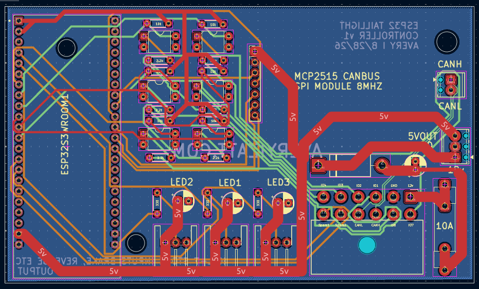
    Unlike a basic LED retrofit, this system is designed more like a rear body control module. Each taillight is treated as its own independently controlled lighting assembly, with stock 12V vehicle signals read through optocouplers for electrical isolation, and CAN bus support included so other modules can eventually monitor system state or issue commands. The project is built in PlatformIO using FastLED and the autowp-mcp2515 library.

    Project Goals

    The main idea behind this build is to create a smarter rear lighting system that still works with the factory car wiring. I wanted something that could read the stock brake, running light, turn signal, and reverse inputs, resolve those into proper light states, and then drive custom addressable LED sections with more modern behavior. That includes things like independent left and right state handling, segmented animation control, thermal protection, and CAN-based monitoring and overrides.

    This also serves as the foundation for a broader electronics modernization plan for the car. The taillight controller is one of the first major modules in that larger system and is intended to be robust enough for real automotive installation rather than just bench testing.

    Core Hardware

    The system is centered around an ESP32-S3 DevKitC-1. Each side of the car uses a custom WS2812B LED assembly with 380 LEDs per side, and each side is electrically isolated from the stock vehicle lighting inputs by its own 4-channel optocoupler module. CAN functionality is handled through an MCP2515 SPI CAN interface. Power is split between 5V for the LED system and 3.3V for the ESP32 logic.

    Main Parts Used

    • ESP32-S3 DevKitC-1
    • WS2812B addressable LEDs
    • Two 4-channel optocoupler modules, one per side
    • MCP2515 CAN bus interface
    • 5V LED power supply
    • 3.3V logic rail for the ESP32
    • Custom wiring and segment interconnects
    • PlatformIO development environment
    • FastLED
    • autowp-mcp2515 library

    LED Layout Per Side

    Each taillight is driven from a single data pin and is made of three chained serpentine LED segments. This gives each side a total of 380 LEDs. The segments are arranged as follows: a top strip with 105 LEDs, a bottom strip with 105 LEDs, and a main section with 170 LEDs. The top strip sits behind a clear diffuser and can display true color, while the bottom strip and main section sit behind red diffusers and are filtered to red-channel output only. Pixel offsets are handled in software so each segment can still be addressed correctly as part of one side.

    Segment Layout Per Side

    SegmentSizeLED CountDiffuserPixel Offset
    SEG_TOP_STRIP21 × 5105Clear, true color0 to 104
    SEG_BOT_STRIP21 × 5105Red only105 to 209
    SEG_MAIN17 × 10170Red only210 to 379

    The software includes an applySegDiffuser() helper in config.h so animations can write the intended color directly without having to manually account for which diffuser is covering each segment. That keeps the animation layer cleaner and makes segment-specific behavior easier to manage.

    GPIO Assignments

    All pin assignments are centralized in src/config.h. The left taillight data line is assigned to GPIO 20, and the right taillight data line is assigned to GPIO 19. Stock signal inputs are split by side and routed through the two optocoupler modules. On the left side, brake is on GPIO 5, running or park is on GPIO 6, turn is on GPIO 4, and reverse is on GPIO 7. On the right side, brake is on GPIO 46, running or park is on GPIO 9, turn is on GPIO 3, and reverse is on GPIO 10. CAN SPI is wired using GPIO 12 for SCK, 13 for MOSI, 14 for MISO, 15 for chip select, and 16 for interrupt.

    Current Pin Map

    SignalGPIO
    Left panel DIN20
    Right panel DIN19
    Left brake5
    Left running or park6
    Left turn4
    Left reverse7
    Right brake46
    Right running or park9
    Right turn3
    Right reverse10
    CAN SCK12
    CAN MOSI13
    CAN MISO14
    CAN CS15
    CAN INT16

    The optocoupler outputs are active low, which means the GPIO reads LOW when the original 12V signal is active. Because of that, all of the input pins are configured with INPUT_PULLUP.

    How the Signal Processing Works

    The taillight controller reads the original rear vehicle lighting signals and debounces them through dedicated input code. Each side then resolves its own state independently based on those four input channels. This means the left and right sides are not forced to mirror each other unless the current condition actually calls for it, such as hazards. That is important for handling mixed states correctly, especially brake plus turn on one side.

    The state priority order is:

    HAZARD > BRAKE_TURN > BRAKE > TURN > REVERSE > RUNNING > OFF

    Light States

    StateDescription
    OFFNo active signals, all LEDs off
    RUNNINGParking or running light active, dim red
    BRAKEBrake input active, bright red
    TURNThis side’s turn signal active, amber sweep
    REVERSEReverse gear active, white output
    BRAKE_TURNBrake and turn active on the same side
    HAZARDBoth turn signals active at once, amber flash

    This state-based design is one of the most important parts of the project. It separates raw electrical inputs from final light behavior, which makes the animation system much easier to extend and debug.

    CAN Bus Support

    An MCP2515 CAN interface is included so that this rear lighting controller can eventually function as part of a larger vehicle electronics network. The CAN bus is configured to run at 500 kbps by default. Three CAN IDs are currently used: 0x100 for state broadcasts, 0x101 for command input, and 0x102 for fault reporting.

    The state broadcast frame reports left and right resolved light state, raw input flags, die temperature, and derate amount. The command frame supports brightness override, animation override, and clearing of overrides. The fault frame is used for diagnostics and can report things like thermal faults, CAN bus-off condition, stuck inputs at boot, watchdog resets, panic resets, and brownout resets.

    CAN Frames

    IDDirectionPurpose
    0x100TXState broadcast
    0x101RXCommands
    0x102TXFault reporting

    Command Frame Functions

    CommandPayloadEffect
    0x01Byte 1 = brightness 0 to 255Set global LED brightness
    0x02Byte 1 = left state, Byte 2 = right stateForce animation override
    0x03NoneClear animation override

    Fault Codes

    CodeNameMeaning
    0x01FAULT_THERMAL_WARNTemperature at or above derate start
    0x02FAULT_THERMAL_CRITICALTemperature at or above thermal critical
    0x03FAULT_CAN_BUS_OFFMCP2515 bus-off condition
    0x04FAULT_INPUT_STUCK_BOOTInput active at boot
    0x05FAULT_WDT_RESETWatchdog reset on previous boot
    0x06FAULT_PANIC_RESETPanic or exception reset on previous boot
    0x07FAULT_BROWNOUT_RESETBrownout or power-loss reset on previous boot

    That CAN support is a big part of what makes this more than just an LED controller. It turns the module into something other ECUs or future controllers can observe and interact with.

    Thermal Protection

    Automotive electronics do not live in a friendly environment, especially once they are mounted in a trunk or body cavity. To help protect the controller, the ESP32-S3 die temperature sensor is monitored continuously in the main loop. Brightness is linearly derated between 65°C and 80°C, and above 85°C the system clamps to a minimum safe brightness of 30 rather than going fully dark. That means the taillights remain visible even under thermal stress, which is much safer than simply shutting the LEDs off.

    Software Structure

    The project is organized into separate files for configuration, inputs, states, per-side taillight control, animations, CAN handling, thermal management, fault handling, and a small bitmap font for matrix text rendering. This keeps the codebase modular and makes it easier to change or expand one part without turning the whole project into one giant file.

    Current Project Layout

    CustomTaillights/
    ├── platformio.ini
    └── src/
        ├── main.cpp
        ├── config.h
        ├── states.h
        ├── inputs.h / .cpp
        ├── taillight.h / .cpp
        ├── animations.h / .cpp
        ├── canbus.h / .cpp
        ├── thermal.h / .cpp
        ├── faults.h
        └── font5x.h / .cpp
    

    More specifically, inputs.cpp handles the debounced dual optocoupler input snapshots, taillight.cpp handles per-side pixel writing, animations.cpp holds the animation framework and built-in effects, and canbus.cpp manages MCP2515 transmit and receive behavior.

    Animation System

    The animation layer is designed so new effects can be added by subclassing the base Animation class and registering the new effect in the animation registry for the desired LightState. Because the TailLight API already understands segment layout and diffuser behavior, new animations can focus on drawing intended colors and movement rather than worrying about the physical color filtering or raw LED mapping every time.

    That setup should make it much easier to keep refining the visual side of the project over time, whether that means improving turn sweeps, changing how brake and running lights layer together, or adding future state-specific effects.

    Installation Notes

    This system is designed around stock 12V rear lighting signals being preserved and sensed, not replaced upstream. Each side has its own optocoupler module for isolation, each taillight has its own dedicated LED data line, and CAN support is already built in for future expansion. The architecture is intentionally modular so the rear lighting system can stand alone now and still integrate with future electronics later.

    This approach also makes troubleshooting cleaner. Electrical inputs, resolved software state, LED output behavior, fault handling, and CAN diagnostics are all separated into their own layers. That should make the final installed system easier to maintain than a one-off lighting retrofit that hides all of the logic in a single file or a nest of ad hoc wiring.

    Why I Built It This Way

    Older cars leave a lot of room for improvement, but I did not want to just bolt in generic LED strips and call it done. I wanted the rear of the car to behave more like a modern electronically controlled system while still respecting the original wiring and the way the car is used. Using the ESP32-S3 gives me enough performance to drive the LED assemblies properly, the optocouplers keep the stock 12V signals electrically isolated from the controller, and the MCP2515 gives me a real path toward turning this into one module of a larger networked electronics system.

    At this stage, the taillight controller is not just a cosmetic project. It is a foundation for a broader modular electronics architecture for the car, starting at the rear and expanding forward over time.


  • Its Alive!

    After months of wrenching, troubleshooting, and more late nights than I can count, the Mustang finally roared back to life.

    This project has been equal parts obsession, education, and exercise in patience. From building the harness to relocating the battery, setting up the Microsquirt ECU, and chasing down electrical gremlins, every system has demanded attention. But hearing it fire up—especially knowing every wire and connection was laid out by hand—made it all worth it.

    The Startup
    I’ll be sharing a video of the first successful start. Even though it’s just idling in the driveway, this moment marks a huge milestone. The Microsquirt is online, sensors are reading correctly, and the ignition finally behaving after sorting out the voltage drop and verifying the coil wiring. It’s not perfectly tuned yet, but the fundamentals are there.

    Battery Relocation
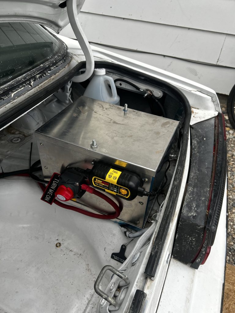
    One of the big changes was moving the battery to the trunk. That meant upgrading to 1/0 gauge cable to handle cranking amps, integrating a cutoff switch, battery charger and re-routing grounds to avoid the voltage drop issues I ran into early on. Even with careful planning, I ended up chasing low voltage at the starter and ECU, if you’re considering a similar setup, be prepared to measure everything twice and still have to improvise.

    Electrical Debugging
    If you’ve been following along, you know the turn signals and hazards decided to quit altogether. After pulling modules apart and checking power feeds, I confirmed the flasher wasn’t the culprit, just a lot of old wiring and tired switches. Replacing the multifunction stalk resolved the high beams refusing to stay on, and I’m still tidying up the last of the loose ends.

    Tuning Learning Curve
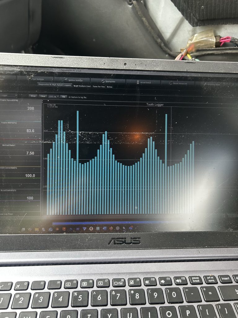
    Moving to a standalone ECU has been a serious learning experience. From setting up the base fuel tables to configuring the trigger wheel and spark output, it’s a process that demands patience and constant iteration. Even now, I’m still refining idle control and enrichment settings. But compared to the old carb setup, the control and data visibility are on another level.


    Next Steps
    Now that it’s running, the next phase is fine-tuning the fuel and ignition maps, tracking down any remaining wiring gremlins, and starting some road tests. There’s still a lot to do before it’s ready for consistent driving, but this was the biggest hurdle.

    I’ll post updates as the tuning progresses. For anyone considering a Microsquirt conversion on an old Foxbody, don’t underestimate the learning curve but also don’t underestimate how satisfying it is when everything finally comes together.


    [Watch the startup video here.]

  • 1989 Foxbody Mustang Introduction Post

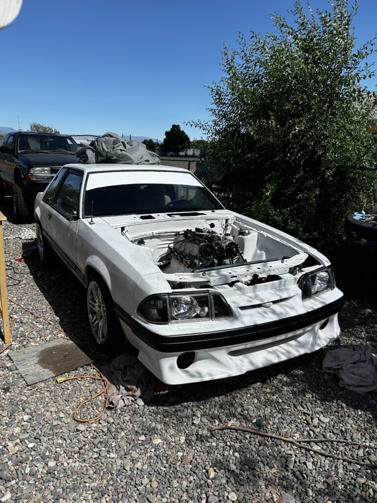
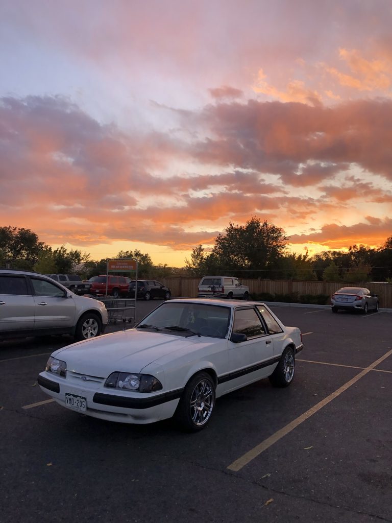
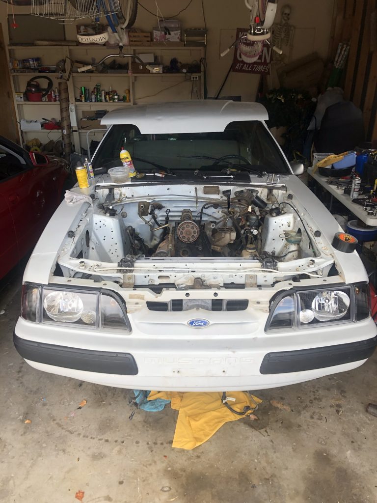
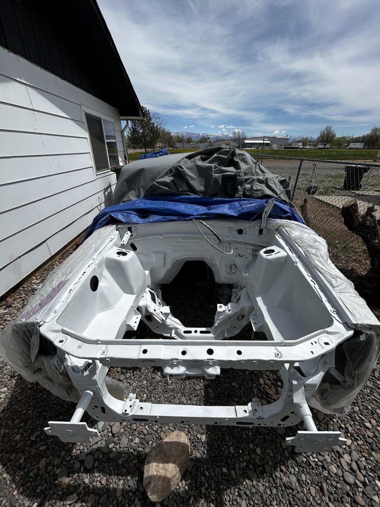
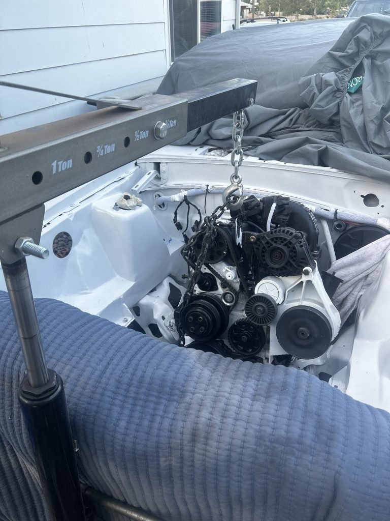
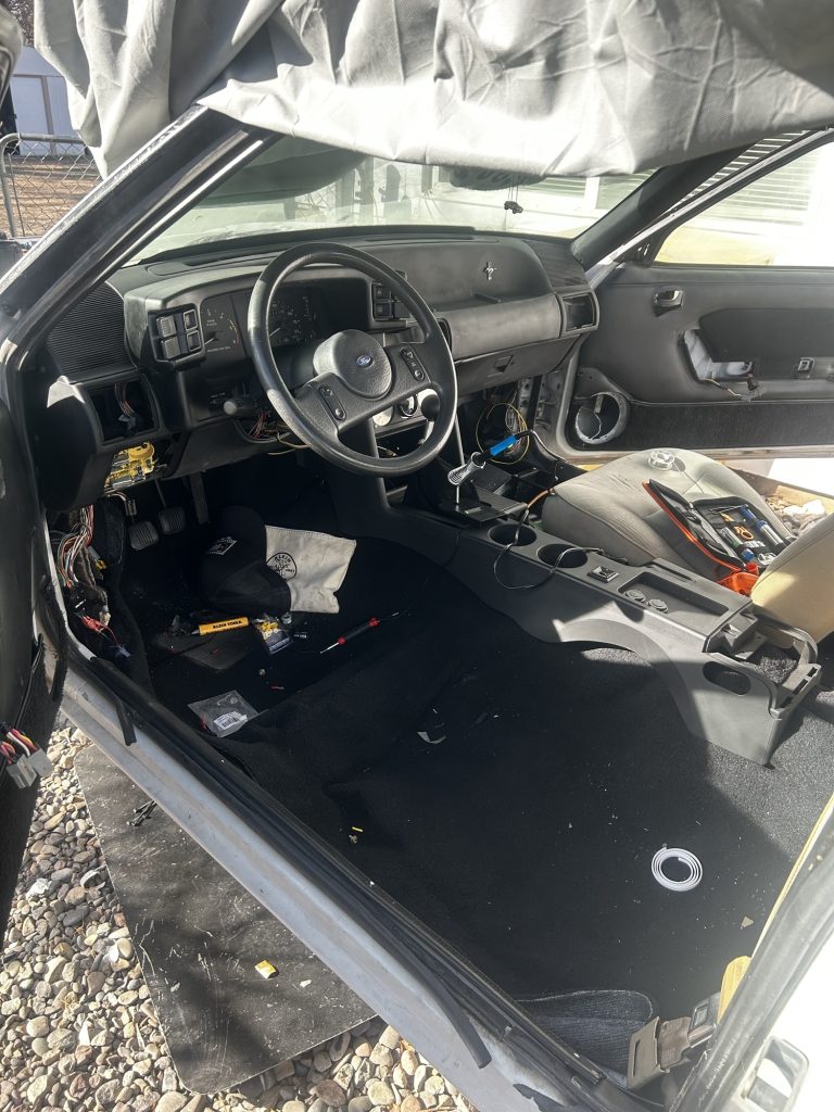
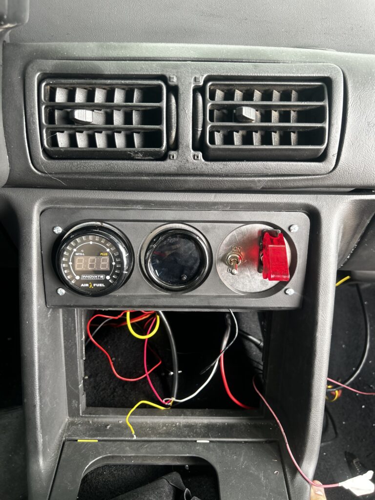
    When people ask where my love for cars and engineering started, I always come back to one thing—my first car: a 1989 Foxbody Mustang LX 2.3L. It wasn’t just a vehicle—it was my blank canvas, my first real hands-on project, and the machine that jumpstarted my obsession with building, tuning, and truly understanding cars from the inside out.

    I got the car when I was still early in my automotive journey. Stock, slow, and in need of serious work—but something about that boxy, raw chassis spoke to me. It wasn’t about how fast it was out of the gate—it was about what it could become. This Mustang became the foundation where I built not just a car, but a deep passion for performance vehicles and electronics integration.

    Over the years, this Foxbody has gone through major transformations:

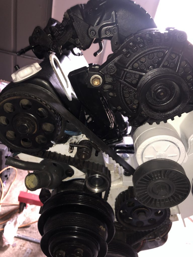
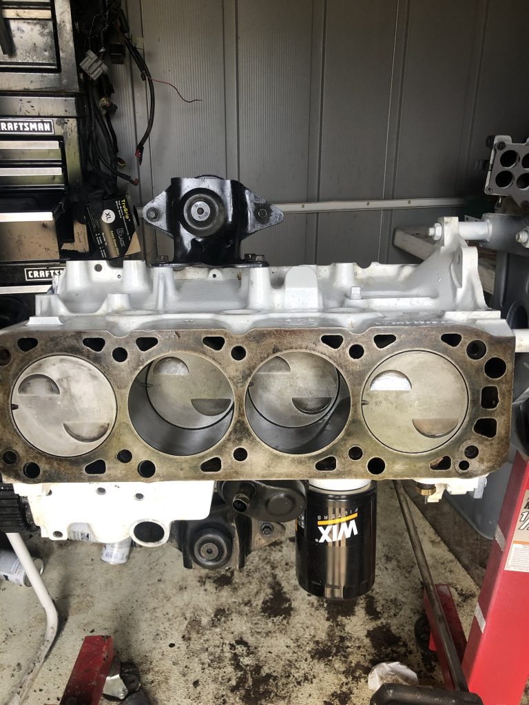
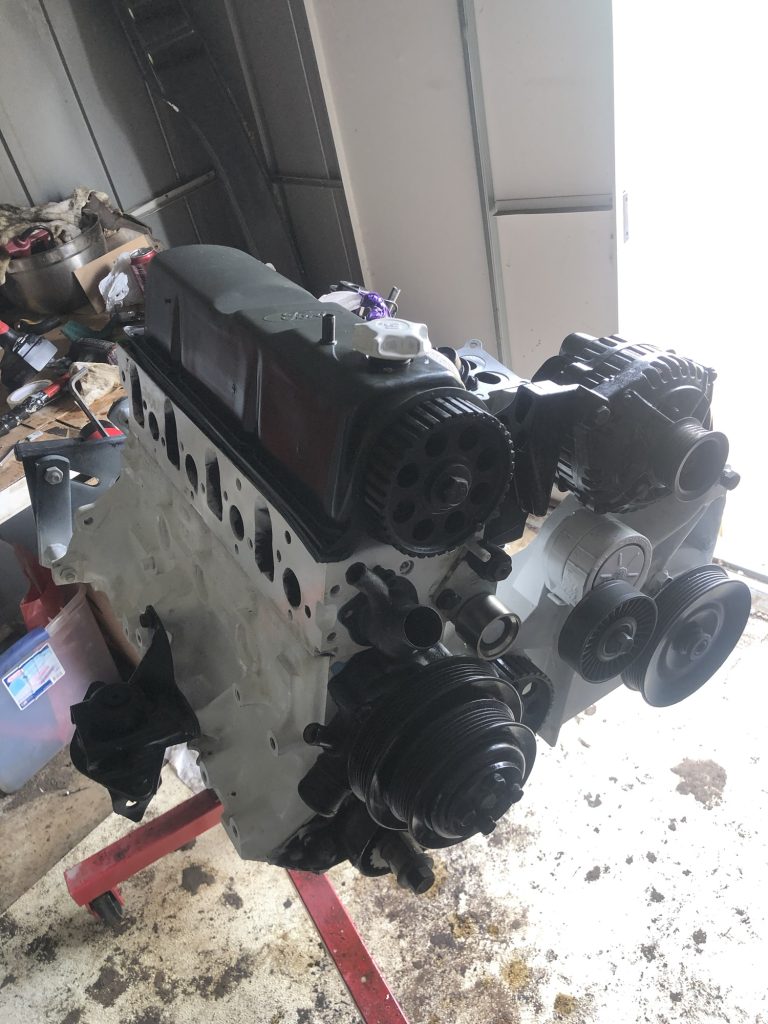
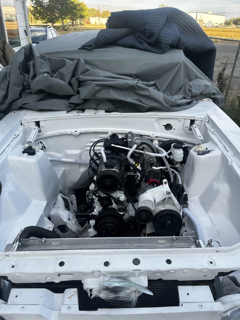
    • I rebuilt the 2.3L Lima engine from the bottom up.
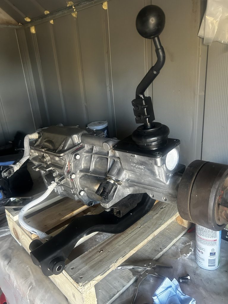
    • Swapped it to a manual transmission.
    • Designed and wired a custom engine harness.
    • Installed a Microsquirt standalone ECU.
    • Converted to coil-on-plug and distributorless ignition.

    Each of these steps taught me more than any textbook could. I dove deep into electrical engineering, engine tuning, diagnostics, fabrication, and the trial-and-error process of building something real.

    This Mustang didn’t just teach me how to work on cars—it showed me how to push through setbacks, learn new systems fast, and take pride in every part of the process. It also gave me the confidence to take on bigger challenges—like designing embedded systems, building robotics, and leading engineering projects.

    This is the first post in a series where I’ll be breaking down the entire journey—from the engine rebuild to the custom ECU and everything in between. If you’re into hands-on learning, standalone ECUs, tuning, or just love a good DIY story, you’ll feel right at home here.