Author: Avery

  • First PCB Update: Firmware

    Bringing the Robotics Controller to Life, Firmware and Software

    In a previous post, I focused on the hardware side of my custom ESP32 S3 robotics controller PCB, including the board layout, grounding strategy, power distribution, and the decisions that went into turning a prototype wiring setup into a real four layer design. That hardware was a huge milestone for me, but a robotics controller is only half finished until the firmware gives it behavior, structure, and a usable interface. The software side is what turns the board from a collection of connected parts into an actual development platform.

    For this stage of the project, I focused on building firmware that was modular, scalable, and practical to work with during development. I did not want a single giant source file with everything packed into one place. Instead, I organized the project into separate modules for motors, servos, ultrasonic sensors, hall sensors, the IMU, buttons, the display, the user interface, robot modes, games, and wireless communication. That structure makes the code easier to understand, easier to test, and much easier to expand later as the board evolves. The firmware is coordinated from a main entry point, while pin assignments and tunable settings are centralized in a config file so the system can be adapted to future hardware revisions without rewriting the whole project.

    One of the biggest goals of this firmware was to make the board useful as both a robotics controller and a self contained demo platform. On the motion control side, the ESP32 S3 uses hardware timed PWM through the LEDC peripheral to drive two DRV8871 motor channels at 20 kHz with 8 bit resolution. That keeps motor control responsive while also pushing the PWM frequency above the normal audible range. The board also supports a standard servo output on GPIO 8, while GPIO 9 is currently repurposed as the potentiometer input for menu navigation and analog controls inside the user interface.

    Sensor support was another major part of the firmware. The board reads four ultrasonic sensors for distance sensing, two hall effect inputs for pulse counting and speed feedback, and an I2C IMU for motion data. In other words, the software is built to support both movement and awareness. That makes the board useful not just for driving motors, but for experimenting with autonomous behavior, closed loop feedback, and navigation concepts.

    I also wanted the board to be easy to interact with without always needing to reflash code or hook up a separate interface. To solve that, I added several layers of user interaction. The first is an onboard TFT display driven over SPI using TFT_eSPI. The current firmware uses a tabbed menu system that runs directly on the display and is controlled with two buttons plus a potentiometer. Through that interface I can view live sensor data, open demos, launch robot modes, scan WiFi networks, look for nearby BLE devices, and navigate through test features without needing an external computer.

    The software also includes a built in wireless dashboard. On boot, the controller creates its own WiFi access point called RoboController and hosts a browser based dashboard at 192.168.4.1. That dashboard includes live sensor data, a WiFi scanner, a BLE radar view, and a control tab for remote operation. Instead of relying on constant polling, the interface pushes live data over WebSocket, which makes it feel much more responsive and interactive. On the control side, the dashboard can send JSON commands for motor drive, servo position, and emergency stop functions. That means the board is not limited to local buttons and a small screen, it can also act like a wireless robotics control node that is easy to test from a phone or laptop.

    BLE support was another area I wanted to build in early. The firmware advertises a custom BLE GATT service that exposes sensor data and accepts motor and servo control writes. That opens the door for mobile apps, sensor streaming, and remote control through BLE tools like nRF Connect. Having both WiFi and BLE built into the same board gives the platform a lot of flexibility, especially for future robotics projects where different communication methods may make sense in different situations.

    One of the most fun parts of this project is that I did not stop at just utility features. I also added a more polished on device experience with multiple demos and even simple games running on the TFT. The firmware includes menu driven screens for live system information, sensor displays, tilt visualization, ultrasonic radar, servo control, and robot mode selection. On top of that, there are games like Snake, Pong, and Asteroids, all rendered through an off screen framebuffer for smooth updates. Those features are obviously not the core purpose of a robotics controller, but they turned out to be a great way to test the display, inputs, UI state machine, timing, and overall firmware structure while making the board much more interesting to interact with.

    From a development standpoint, I built the project around PlatformIO, which makes library management and builds much easier to handle. The firmware pulls in libraries like ESP32Servo, TFT_eSPI, AsyncTCP, ESPAsyncWebServer, and NimBLE Arduino. Using a structured toolchain like this makes the project more portable and easier to maintain than an ad hoc sketch with manual dependency management.

    What I like most about this phase of the project is that it shows the board is more than just a PCB layout exercise. The hardware and software were designed to work together as a reusable robotics platform. The board can drive motors, read sensors, host a display UI, create its own wireless dashboard, expose BLE services, and support future expansion through broken out GPIO. That combination is what really makes it feel like a complete system rather than just another microcontroller board. The hardware post was about building the foundation. This firmware phase is about giving that foundation behavior.

    There is still plenty I want to improve. I want to keep refining the robot modes, continue testing the wireless control features, and push the platform further as both a practical robotics controller and a polished demonstration board. Even so, getting this firmware architecture working has already been a huge step forward. It taught me a lot about structuring embedded software, building usable interfaces on constrained hardware, and designing systems that are easier to grow over time.

    This project started as a custom board to clean up wiring and consolidate hardware. Now it is becoming a full robotics platform, with hardware, firmware, wireless control, and a user interface all designed to work together.

  • Smart Taillight Controller for a 1989 Fox Body Mustang


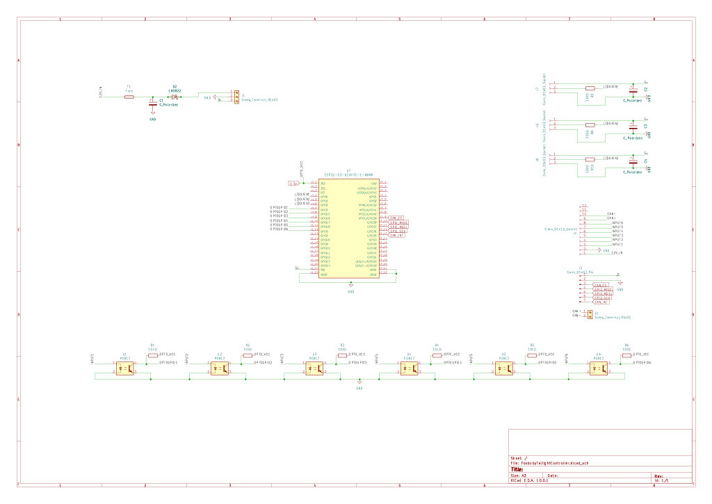
    Modernizing the rear lighting of an older car is one of those projects that seems simple at first, but quickly turns into a much bigger electrical, software, and packaging challenge. This project is my custom taillight controller for a 1989 Fox Body Mustang, built around an ESP32-S3 and fully custom WS2812B LED assemblies. The goal is to preserve the function of the factory lighting signals while replacing the original rear lighting behavior with a programmable, modular system that is cleaner, more flexible, and easier to expand in the future.

    Unlike a basic LED retrofit, this system is designed more like a rear body control module. Each taillight is treated as its own independently controlled lighting assembly, with stock 12V vehicle signals read through optocouplers for electrical isolation, and CAN bus support included so other modules can eventually monitor system state or issue commands. The project is built in PlatformIO using FastLED and the autowp-mcp2515 library.

    Project Goals

    The main idea behind this build is to create a smarter rear lighting system that still works with the factory car wiring. I wanted something that could read the stock brake, running light, turn signal, and reverse inputs, resolve those into proper light states, and then drive custom addressable LED sections with more modern behavior. That includes things like independent left and right state handling, segmented animation control, thermal protection, and CAN-based monitoring and overrides.

    This also serves as the foundation for a broader electronics modernization plan for the car. The taillight controller is one of the first major modules in that larger system and is intended to be robust enough for real automotive installation rather than just bench testing.

    Core Hardware

    The system is centered around an ESP32-S3 DevKitC-1. Each side of the car uses a custom WS2812B LED assembly with 380 LEDs per side, and each side is electrically isolated from the stock vehicle lighting inputs by its own 4-channel optocoupler module. CAN functionality is handled through an MCP2515 SPI CAN interface. Power is split between 5V for the LED system and 3.3V for the ESP32 logic.

    Main Parts Used

    • ESP32-S3 DevKitC-1
    • WS2812B addressable LEDs
    • Two 4-channel optocoupler modules, one per side
    • MCP2515 CAN bus interface
    • 5V LED power supply
    • 3.3V logic rail for the ESP32
    • Custom wiring and segment interconnects
    • PlatformIO development environment
    • FastLED
    • autowp-mcp2515 library

    LED Layout Per Side

    Each taillight is driven from a single data pin and is made of three chained serpentine LED segments. This gives each side a total of 380 LEDs. The segments are arranged as follows: a top strip with 105 LEDs, a bottom strip with 105 LEDs, and a main section with 170 LEDs. The top strip sits behind a clear diffuser and can display true color, while the bottom strip and main section sit behind red diffusers and are filtered to red-channel output only. Pixel offsets are handled in software so each segment can still be addressed correctly as part of one side.

    Segment Layout Per Side

    SegmentSizeLED CountDiffuserPixel Offset
    SEG_TOP_STRIP21 × 5105Clear, true color0 to 104
    SEG_BOT_STRIP21 × 5105Red only105 to 209
    SEG_MAIN17 × 10170Red only210 to 379

    The software includes an applySegDiffuser() helper in config.h so animations can write the intended color directly without having to manually account for which diffuser is covering each segment. That keeps the animation layer cleaner and makes segment-specific behavior easier to manage.

    GPIO Assignments

    All pin assignments are centralized in src/config.h. The left taillight data line is assigned to GPIO 20, and the right taillight data line is assigned to GPIO 19. Stock signal inputs are split by side and routed through the two optocoupler modules. On the left side, brake is on GPIO 5, running or park is on GPIO 6, turn is on GPIO 4, and reverse is on GPIO 7. On the right side, brake is on GPIO 46, running or park is on GPIO 9, turn is on GPIO 3, and reverse is on GPIO 10. CAN SPI is wired using GPIO 12 for SCK, 13 for MOSI, 14 for MISO, 15 for chip select, and 16 for interrupt.

    Current Pin Map

    SignalGPIO
    Left panel DIN20
    Right panel DIN19
    Left brake5
    Left running or park6
    Left turn4
    Left reverse7
    Right brake46
    Right running or park9
    Right turn3
    Right reverse10
    CAN SCK12
    CAN MOSI13
    CAN MISO14
    CAN CS15
    CAN INT16

    The optocoupler outputs are active low, which means the GPIO reads LOW when the original 12V signal is active. Because of that, all of the input pins are configured with INPUT_PULLUP.

    How the Signal Processing Works

    The taillight controller reads the original rear vehicle lighting signals and debounces them through dedicated input code. Each side then resolves its own state independently based on those four input channels. This means the left and right sides are not forced to mirror each other unless the current condition actually calls for it, such as hazards. That is important for handling mixed states correctly, especially brake plus turn on one side.

    The state priority order is:

    HAZARD > BRAKE_TURN > BRAKE > TURN > REVERSE > RUNNING > OFF

    Light States

    StateDescription
    OFFNo active signals, all LEDs off
    RUNNINGParking or running light active, dim red
    BRAKEBrake input active, bright red
    TURNThis side’s turn signal active, amber sweep
    REVERSEReverse gear active, white output
    BRAKE_TURNBrake and turn active on the same side
    HAZARDBoth turn signals active at once, amber flash

    This state-based design is one of the most important parts of the project. It separates raw electrical inputs from final light behavior, which makes the animation system much easier to extend and debug.

    CAN Bus Support

    An MCP2515 CAN interface is included so that this rear lighting controller can eventually function as part of a larger vehicle electronics network. The CAN bus is configured to run at 500 kbps by default. Three CAN IDs are currently used: 0x100 for state broadcasts, 0x101 for command input, and 0x102 for fault reporting.

    The state broadcast frame reports left and right resolved light state, raw input flags, die temperature, and derate amount. The command frame supports brightness override, animation override, and clearing of overrides. The fault frame is used for diagnostics and can report things like thermal faults, CAN bus-off condition, stuck inputs at boot, watchdog resets, panic resets, and brownout resets.

    CAN Frames

    IDDirectionPurpose
    0x100TXState broadcast
    0x101RXCommands
    0x102TXFault reporting

    Command Frame Functions

    CommandPayloadEffect
    0x01Byte 1 = brightness 0 to 255Set global LED brightness
    0x02Byte 1 = left state, Byte 2 = right stateForce animation override
    0x03NoneClear animation override

    Fault Codes

    CodeNameMeaning
    0x01FAULT_THERMAL_WARNTemperature at or above derate start
    0x02FAULT_THERMAL_CRITICALTemperature at or above thermal critical
    0x03FAULT_CAN_BUS_OFFMCP2515 bus-off condition
    0x04FAULT_INPUT_STUCK_BOOTInput active at boot
    0x05FAULT_WDT_RESETWatchdog reset on previous boot
    0x06FAULT_PANIC_RESETPanic or exception reset on previous boot
    0x07FAULT_BROWNOUT_RESETBrownout or power-loss reset on previous boot

    That CAN support is a big part of what makes this more than just an LED controller. It turns the module into something other ECUs or future controllers can observe and interact with.

    Thermal Protection

    Automotive electronics do not live in a friendly environment, especially once they are mounted in a trunk or body cavity. To help protect the controller, the ESP32-S3 die temperature sensor is monitored continuously in the main loop. Brightness is linearly derated between 65°C and 80°C, and above 85°C the system clamps to a minimum safe brightness of 30 rather than going fully dark. That means the taillights remain visible even under thermal stress, which is much safer than simply shutting the LEDs off.

    Software Structure

    The project is organized into separate files for configuration, inputs, states, per-side taillight control, animations, CAN handling, thermal management, fault handling, and a small bitmap font for matrix text rendering. This keeps the codebase modular and makes it easier to change or expand one part without turning the whole project into one giant file.

    Current Project Layout

    CustomTaillights/
    ├── platformio.ini
    └── src/
        ├── main.cpp
        ├── config.h
        ├── states.h
        ├── inputs.h / .cpp
        ├── taillight.h / .cpp
        ├── animations.h / .cpp
        ├── canbus.h / .cpp
        ├── thermal.h / .cpp
        ├── faults.h
        └── font5x.h / .cpp
    

    More specifically, inputs.cpp handles the debounced dual optocoupler input snapshots, taillight.cpp handles per-side pixel writing, animations.cpp holds the animation framework and built-in effects, and canbus.cpp manages MCP2515 transmit and receive behavior.

    Animation System

    The animation layer is designed so new effects can be added by subclassing the base Animation class and registering the new effect in the animation registry for the desired LightState. Because the TailLight API already understands segment layout and diffuser behavior, new animations can focus on drawing intended colors and movement rather than worrying about the physical color filtering or raw LED mapping every time.

    That setup should make it much easier to keep refining the visual side of the project over time, whether that means improving turn sweeps, changing how brake and running lights layer together, or adding future state-specific effects.

    Installation Notes

    This system is designed around stock 12V rear lighting signals being preserved and sensed, not replaced upstream. Each side has its own optocoupler module for isolation, each taillight has its own dedicated LED data line, and CAN support is already built in for future expansion. The architecture is intentionally modular so the rear lighting system can stand alone now and still integrate with future electronics later.

    This approach also makes troubleshooting cleaner. Electrical inputs, resolved software state, LED output behavior, fault handling, and CAN diagnostics are all separated into their own layers. That should make the final installed system easier to maintain than a one-off lighting retrofit that hides all of the logic in a single file or a nest of ad hoc wiring.

    Why I Built It This Way

    Older cars leave a lot of room for improvement, but I did not want to just bolt in generic LED strips and call it done. I wanted the rear of the car to behave more like a modern electronically controlled system while still respecting the original wiring and the way the car is used. Using the ESP32-S3 gives me enough performance to drive the LED assemblies properly, the optocouplers keep the stock 12V signals electrically isolated from the controller, and the MCP2515 gives me a real path toward turning this into one module of a larger networked electronics system.

    At this stage, the taillight controller is not just a cosmetic project. It is a foundation for a broader modular electronics architecture for the car, starting at the rear and expanding forward over time.


  • First Custom PCB Project

    ESP32-S3 Robotics Controller Hub

    One of the biggest milestones in my recent work has been designing my first fully custom PCB: a 4-layer, ESP32-S3 based robotics controller hub. This board was built to consolidate the many separate modules, wiring harnesses, and prototype systems I had been using into a single, clean, and scalable platform for robotics development.

    Design Overview

    At the core of the system is the ESP32-S3, chosen for its processing capability, flexible GPIO matrix, integrated WiFi and Bluetooth, and strong support for real-time control tasks. Around it, I designed a complete control and sensing ecosystem intended for mobile robotics applications.

    The board integrates:

    • Dual DRV8871 motor drivers for bidirectional DC motor control
    • Support for two servo outputs with PWM control
    • Four ultrasonic sensor interfaces for environmental awareness
    • Two hall effect sensor inputs for feedback such as wheel speed or position tracking
    • A SPI-connected display for onboard telemetry, debugging, and UI
    • Onboard linear regulation and power distribution
    • Expansion headers for unused GPIO to support future features

    The goal was not just to “make it work,” but to build something robust, reusable, and electrically sound.


    Moving from Wiring to PCB Design

    Prior to this board, most of my systems were built using breadboards or modular components. While flexible, those setups quickly became unreliable and difficult to maintain, especially when dealing with motors and multiple sensors. This project was my transition into designing a dedicated hardware platform.

    The schematic design phase was relatively straightforward. The real learning curve came during PCB layout.


    4-Layer Stackup and Grounding Strategy

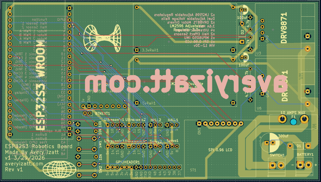
    This board uses a 4-layer stackup, which allowed for a much more controlled and professional layout compared to a 2-layer design. The layers were organized as:

    • Top Layer: signal routing and high-current paths
    • Inner Layer 1: solid ground plane
    • Inner Layer 2: power distribution (VM and regulated rails)
    • Bottom Layer: additional signal routing and localized pours

    A continuous ground plane was one of the most important design decisions. Instead of routing ground as traces, I used large copper pours and stitching vias to create a low-impedance return path across the entire board. This significantly improves noise performance and reduces the likelihood of instability, especially with switching motor loads.

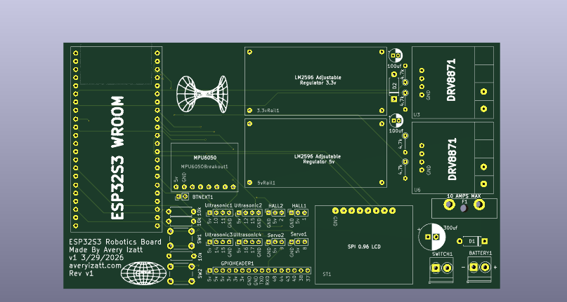
    PCB Front View

    High-Current Design Considerations

    Driving motors introduces large and rapidly changing currents, which can easily create voltage drops, EMI, and system instability if not handled properly.

    To address this:

    • High-current paths were routed using wide copper traces and local pours
    • Motor driver ground connections were reinforced with multiple stitching vias into the ground plane
    • VM (motor supply voltage) was kept as a controlled, localized copper region rather than a full-plane pour
    • Return paths were kept as short and direct as possible to minimize loop area

    One key concept I learned was that current does not just follow the forward path, it follows a loop. Designing tight, low-impedance loops between VM and GND was critical for stable operation.


    Decoupling and Noise Reduction

    Decoupling capacitors were placed strategically throughout the board, particularly:

    • Close to the ESP32-S3 power pins
    • Adjacent to each motor driver
    • Between VM and ground near high-current switching areas

    Both bulk capacitors and small ceramic capacitors were used to handle different frequency ranges of noise. Placement was just as important as value. Keeping these components physically close to the devices they support dramatically improves effectiveness.


    Signal Integrity and Peripheral Integration

    With a mix of analog-like signals (ultrasonic sensors), digital inputs (hall sensors, buttons), PWM outputs (servos), and high-speed communication (SPI display, I2C IMU), careful routing was required.

    Key considerations included:

    • Keeping noisy motor and power traces away from sensitive sensor lines
    • Using short, direct routes for SPI signals to the display
    • Maintaining clean pull-up configurations for I2C communication
    • Ensuring proper voltage compatibility, particularly for ultrasonic sensor echo lines

    Expandability and Practical Design

    A portion of the design was dedicated to future-proofing. Unused GPIO pins were broken out into a dedicated header along with power and ground, allowing additional modules or features to be added without redesigning the board.

    This was a deliberate choice to make the board not just a one-off project, but a reusable platform.


    What I Learned

    This project reinforced that PCB design is not just about making electrical connections, it is about managing current flow, noise, and physical layout in a way that supports reliable operation.

    Some of the biggest takeaways:

    • Grounding strategy is critical and should be planned early
    • High-current paths must be treated differently than signal traces
    • Component placement often matters more than routing
    • Decoupling and return paths directly affect system stability
    • Planning for expansion saves time in future iterations

    Looking Forward

    This board represents a major step forward in both my electronics design and system integration skills. It replaces a complex, error-prone wiring setup with a compact, reliable controller that can serve as the foundation for future robotics projects.

    The next phase will involve assembling, testing, and iterating on the design. I expect there will be improvements to make, but that is part of the process.

    Designing this board has been one of the most rewarding technical challenges I’ve taken on so far, and it sets the stage for more advanced and refined hardware in the future!

    How to Use the Robotics Controller

    This controller is designed to act as a central hub for motor control, sensing, and user interaction. The system is built around the ESP32-S3 and uses a mix of PWM, digital I/O, I2C, and SPI peripherals.

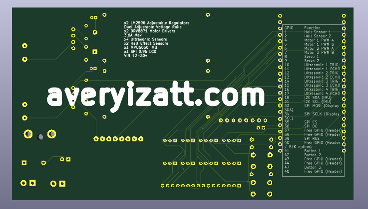
    GPIO Pin Reference

    GPIO | Function
    1 | Hall Sensor 1
    2 | Hall Sensor 2
    4 | Motor 1 PWM A
    5 | Motor 1 PWM B
    6 | Motor 2 PWM A
    7 | Motor 2 PWM B
    8 | Servo 1
    9 | Servo 2
    10 | Ultrasonic 1 TRIG
    11 | Ultrasonic 1 ECHO
    12 | Ultrasonic 2 TRIG
    13 | Ultrasonic 2 ECHO
    14 | Ultrasonic 3 TRIG
    15 | Ultrasonic 3 ECHO
    16 | Ultrasonic 4 TRIG
    17 | Ultrasonic 4 ECHO
    18 | I2C SDA (IMU)
    21 | I2C SCL (IMU)
    33 | SPI MOSI (Display SDA)
    34 | SPI SCLK (Display SCL)
    35 | SPI CS
    36 | SPI DC
    39 | SPI RES
    41 | Button 1
    42 | Button 2
    47 | Button 3

    Additional GPIO (37, 38, 40, 43, 44, 48) are exposed via header for expansion.

    Motor Control (DRV8871)

    Motor 1: GPIO 4 (PWM A), GPIO 5 (PWM B)
    Motor 2: GPIO 6 (PWM A), GPIO 7 (PWM B)

    Control:

    • PWM A high, PWM B low → forward
    • PWM A low, PWM B high → reverse
    • Both low → coast
    • Both high → brake

    Servo Outputs

    Servo 1 → GPIO 8
    Servo 2 → GPIO 9

    Standard 50 Hz PWM:

    • ~1.0 ms pulse → 0°
    • ~1.5 ms → center
    • ~2.0 ms → 180°

    Ultrasonic Sensors

    TRIG pins: GPIO 10, 12, 14, 16
    ECHO pins: GPIO 11, 13, 15, 17

    Operation:

    1. Send 10 µs pulse on TRIG
    2. Measure pulse width on ECHO
    3. Convert to distance

    Hall Effect Sensors

    Hall 1 → GPIO 1
    Hall 2 → GPIO 2

    Used for:

    • Speed measurement
    • Rotation counting
    • Position feedback

    IMU (I2C)

    SDA → GPIO 18
    SCL → GPIO 21

    SPI Display

    MOSI (SDA) → GPIO 33
    SCLK (SCL) → GPIO 34
    CS → GPIO 35
    DC → GPIO 36
    RES → GPIO 39

    Push Buttons

    Button 1 → GPIO 41
    Button 2 → GPIO 42
    Button 3 → GPIO 47

    Use:
    pinMode(pin, INPUT_PULLUP);

    Expansion Header

    Available GPIO:
    37, 38, 40, 43, 44, 48

    Firmware Template

    https://github.com/averyizatt/ESP32BasedRobiticsPCB

  • Project Update: Building, Leading, and Getting Things Running

    The past few months have been a mix of technical work, leadership, and finally getting some long-term projects across the finish line. A lot of what I’ve been doing has shifted from just building individual components to managing systems, teams, and real-world constraints.

    IEEE Club & COSGC Rover

    Alongside technical work, I’ve been managing the IEEE club, organizing meetings, planning workshops, and coordinating trips and outreach events. Balancing that with engineering work has been a challenge, but it’s also been a great way to build experience beyond just the technical side.

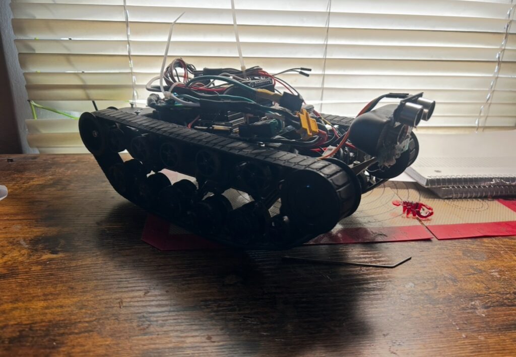
    At the same time, I’ve continued working on the COSGC rover project. After simplifying the drivetrain to a skid-steer design, I’ve been focusing on making the system more reliable and practical. A big part of that has been designing a self-righting mechanism, which turned into a deeper dive into torque, leverage, and mechanical advantage than I initially expected.

    What started as a simple idea quickly became an exercise in real engineering tradeoffs. Longer arms gave more reach but not enough force, while shorter arms had the opposite problem. That pushed me toward rethinking the geometry and exploring better ways to apply force rather than just increasing power.

    Electronics, Power, and Control

    On the electronics side, I’ve been refining control systems using Arduino-based setups and working through proper power distribution. Running a 24V system with buck converters for logic and peripherals has been a big part of this, along with learning how important things like decoupling and bulk capacitance are when motors and servos are involved.

    I’ve also been experimenting with using current sensing to estimate load on actuators. It’s a simple concept, but it adds a layer of awareness to the system that opens up better control and protection strategies.

    Sensors & Real-World Testing

    Another focus has been testing sensors in less-than-ideal environments. Comparing ultrasonic and optical distance sensing highlighted how much conditions like sunlight and uneven terrain can affect performance.

    It’s been a good reminder that designs need to work outside of controlled environments, especially for a rover that’s expected to operate on varied surfaces.

    Mustang Project

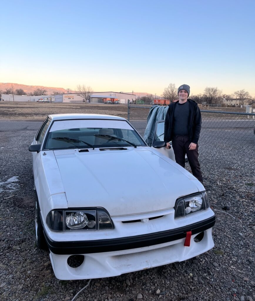
    Outside of robotics, I’ve been putting in a lot of work on my 1989 Mustang. After a long process of rebuilding and tuning, the car is now fully running and driving under a self-tuned ECU setup.

    Getting it to this point involved dialing in fuel, ignition, and overall system behavior, and it’s been one of the most rewarding parts of the past few months to see it finally come together and operate the way it should.

    What I’ve Been Learning

    Across all of these projects, the biggest takeaway has been that good engineering isn’t about forcing things to work, it’s about designing them so they work naturally.

    Whether it’s managing torque through better geometry stabilizing electronics with proper power design or balancing technical work with leadership responsibilities, the focus has been on building systems that are reliable, not just functional.

  • Its Alive!

    After months of wrenching, troubleshooting, and more late nights than I can count, the Mustang finally roared back to life.

    This project has been equal parts obsession, education, and exercise in patience. From building the harness to relocating the battery, setting up the Microsquirt ECU, and chasing down electrical gremlins, every system has demanded attention. But hearing it fire up—especially knowing every wire and connection was laid out by hand—made it all worth it.

    The Startup
    I’ll be sharing a video of the first successful start. Even though it’s just idling in the driveway, this moment marks a huge milestone. The Microsquirt is online, sensors are reading correctly, and the ignition finally behaving after sorting out the voltage drop and verifying the coil wiring. It’s not perfectly tuned yet, but the fundamentals are there.

    Battery Relocation
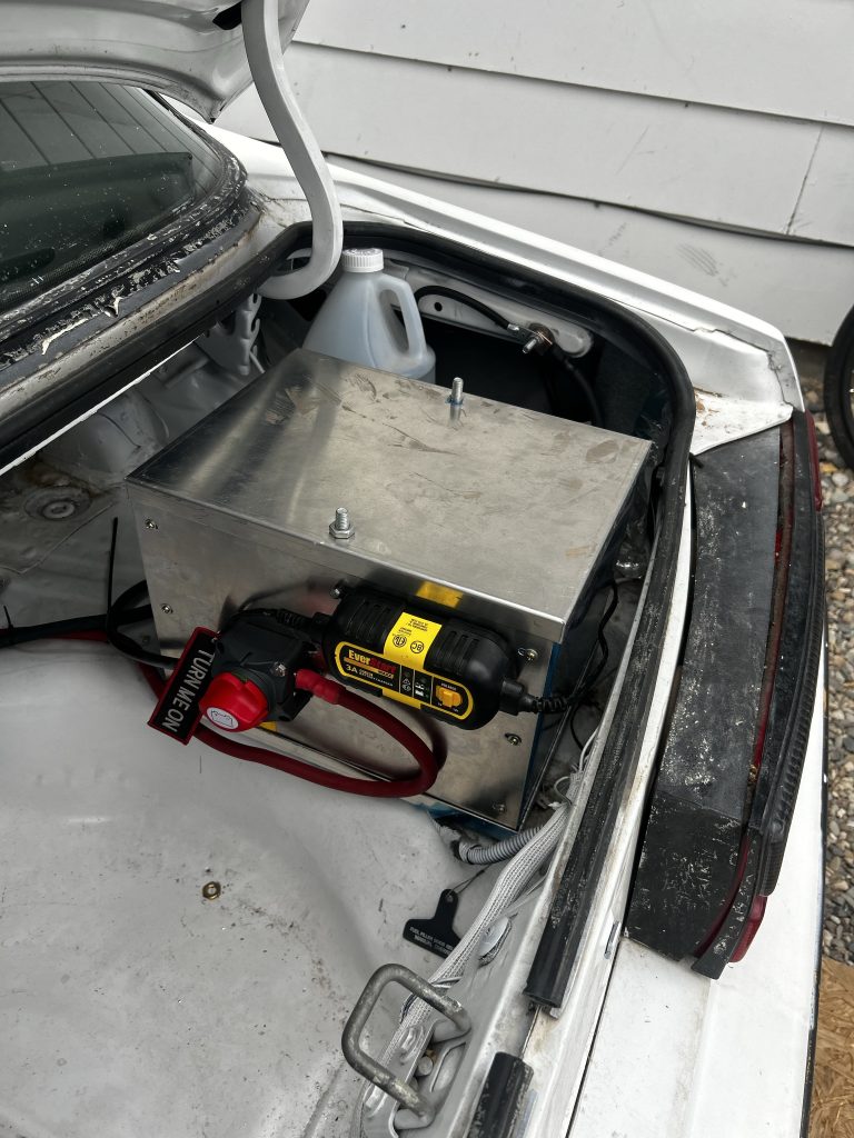
    One of the big changes was moving the battery to the trunk. That meant upgrading to 1/0 gauge cable to handle cranking amps, integrating a cutoff switch, battery charger and re-routing grounds to avoid the voltage drop issues I ran into early on. Even with careful planning, I ended up chasing low voltage at the starter and ECU, if you’re considering a similar setup, be prepared to measure everything twice and still have to improvise.

    Electrical Debugging
    If you’ve been following along, you know the turn signals and hazards decided to quit altogether. After pulling modules apart and checking power feeds, I confirmed the flasher wasn’t the culprit, just a lot of old wiring and tired switches. Replacing the multifunction stalk resolved the high beams refusing to stay on, and I’m still tidying up the last of the loose ends.

    Tuning Learning Curve
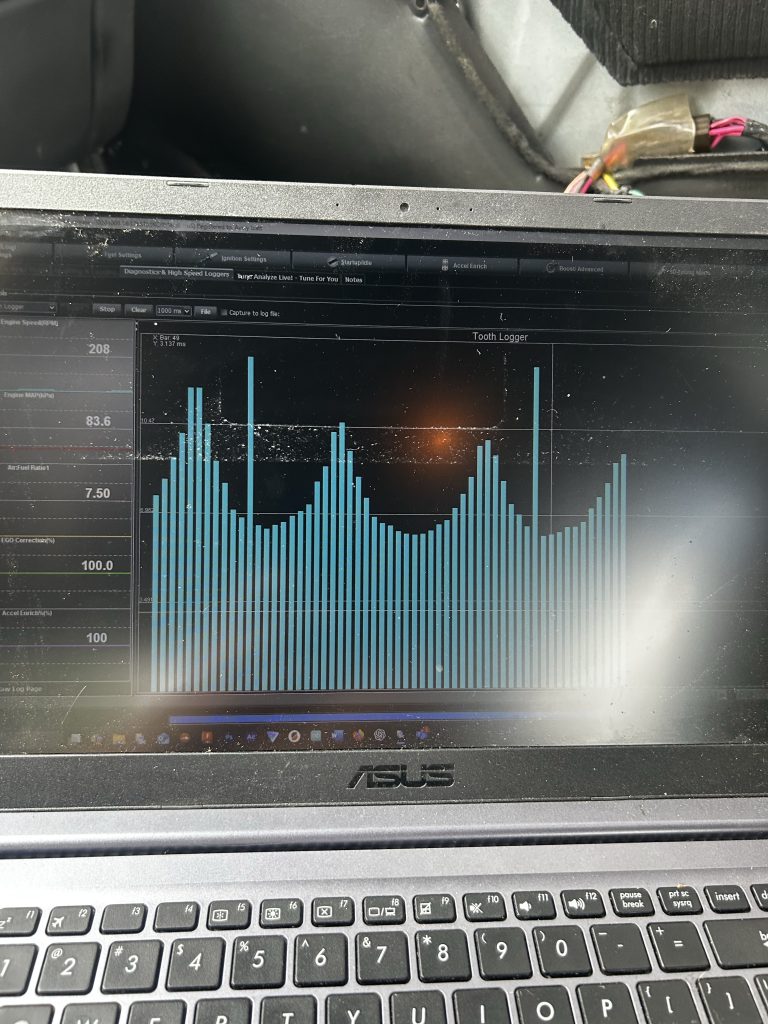
    Moving to a standalone ECU has been a serious learning experience. From setting up the base fuel tables to configuring the trigger wheel and spark output, it’s a process that demands patience and constant iteration. Even now, I’m still refining idle control and enrichment settings. But compared to the old carb setup, the control and data visibility are on another level.


    Next Steps
    Now that it’s running, the next phase is fine-tuning the fuel and ignition maps, tracking down any remaining wiring gremlins, and starting some road tests. There’s still a lot to do before it’s ready for consistent driving, but this was the biggest hurdle.

    I’ll post updates as the tuning progresses. For anyone considering a Microsquirt conversion on an old Foxbody, don’t underestimate the learning curve but also don’t underestimate how satisfying it is when everything finally comes together.


    [Watch the startup video here.]

  • Custom Car Stereo with Tuning Integration

    Raspberry Pi-Based Digital Dash & ECU Tuning Interface for a Race Car

    This project transforms a Raspberry Pi into a powerful, multifunctional infotainment and tuning system for my 1989 Foxbody Mustang race car. It replicates the functionality of expensive standalone systems using open-source tools and custom hardware integration, all on a budget.


    Overview

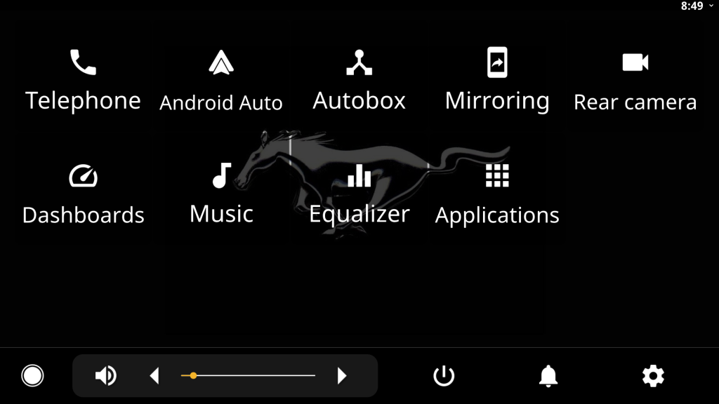
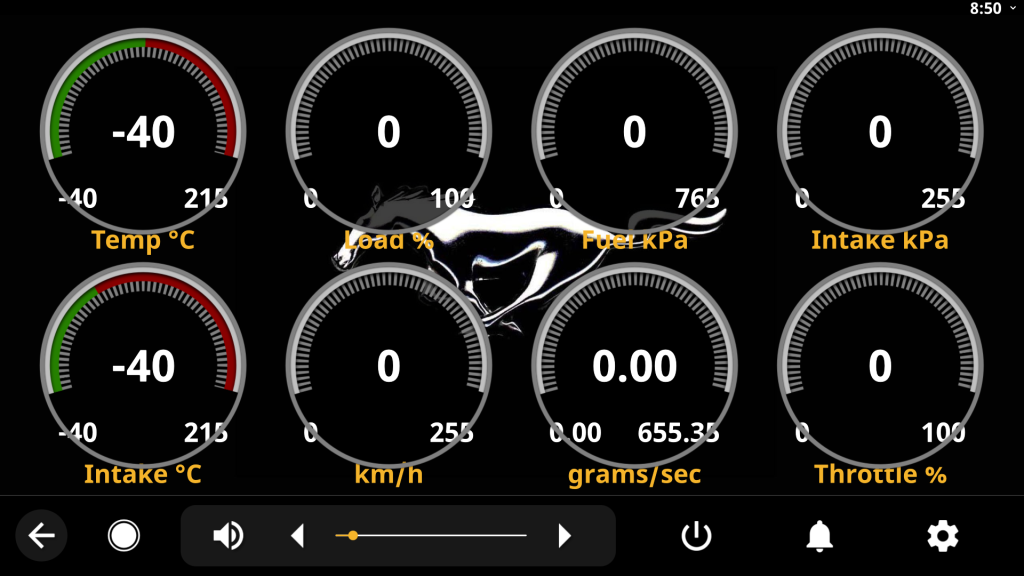
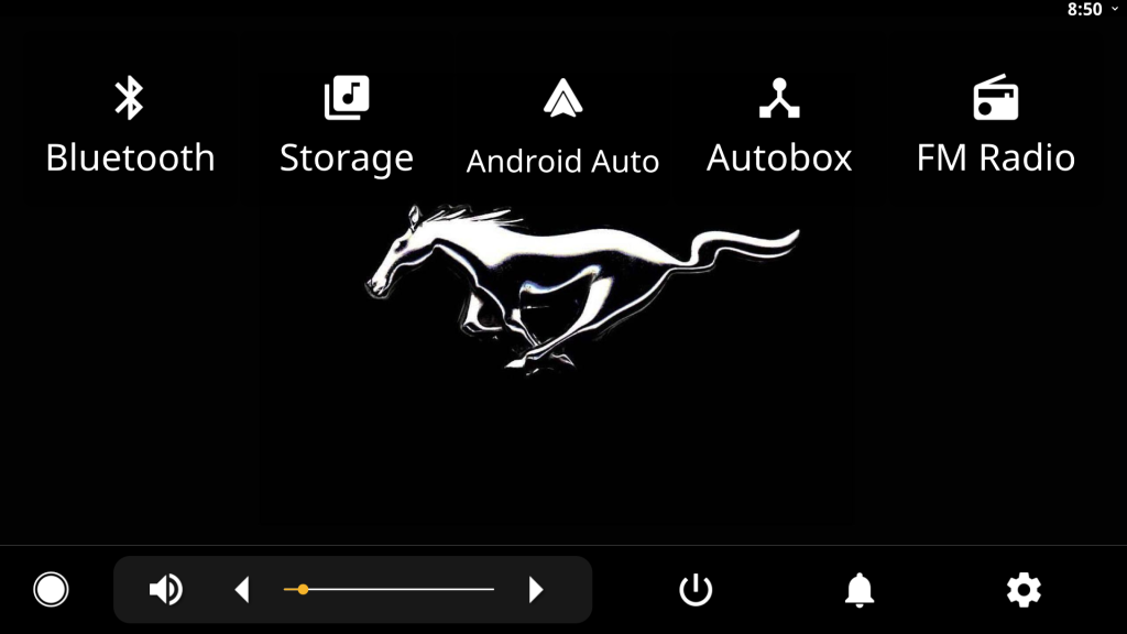
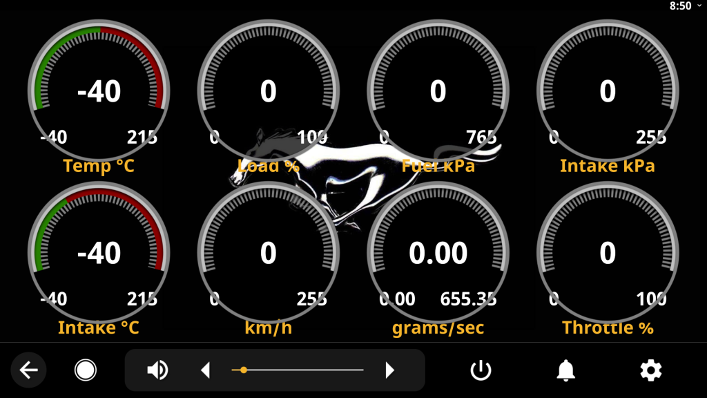
    I adapted an open-source Android Auto emulator called OpenAuto to work seamlessly in my custom race car environment. It provides a full graphical interface for music, navigation, and rear camera integration, while also acting as a direct tuning interface with TunerStudio, enabling real-time ECU adjustments without needing a laptop.

    Audio is routed through a compact amp module connected to the car’s factory speaker system, offering both clarity and volume control. This setup mimics the experience of high-end race car data systems but at a fraction of the cost.


    Key Features

    • TunerStudio Integration: The Raspberry Pi connects to my Microsquirt ECU over USB, letting me monitor, log, and tune the engine directly through TunerStudio on the Pi.
    • OpenAuto Interface: I customized OpenAuto to act as a driver-friendly infotainment system, with clean visuals and touch support.
    • Rear Camera Support: A libcamera-compatible rear camera streams to the dash. A GPIO-controlled trigger (via reverse signal or button) activates the view using libcamera-vid and ffplay.
    • Graceful Shutdown Logic: A pair of relays (12V and 5V) with a delay module safely shuts down the Pi when ignition is turned off. This replicates OEM-style system behavior and protects the SD card from corruption.
    • Audio Integration: A compact 12V-powered audio amplifier module routes the Pi’s sound output through the car’s speaker system.

    Bill of Materials (BOM)

    ItemDescriptionNotes
    Raspberry Pi 4 (2GB or higher)Main system boardRunning OpenAuto & TunerStudio
    MicroSD Card (32GB+)Storage for OS and softwareHigh-endurance card preferred
    12V to 5V Buck ConverterPowers the PiConnected through 5V delay relay
    12V RelayMonitors ignition and triggers shutdown logicACC line goes to pin 85
    5V Time Delay Relay ModuleMaintains power to Pi for safe shutdownReceives trigger from Pi GPIO
    Compact Audio AmplifierRoutes Pi audio to car speakersPowered by 12V supply
    Rear Camera (IMX219 or similar)High-quality CSI cameraStreamed using libcamera-vid
    Display (HDMI or DSI)Dash-mounted screenNon-touch or touch-capable options available
    USB GPS (optional)For accurate navigation/tuning logsIntegrates into OpenAuto or TunerStudio logging
    Misc Wiring, Fuses, ConnectorsFor all power, GPIO, and AV routingInclude fuse on VREF and Pi power lines

    How It Works

    1. Startup Sequence: When the ignition (ACC) is turned on, the 12V relay powers up and sends power to the Pi via a 5V converter and delayed relay. The Pi boots into OpenAuto and launches TunerStudio in the background.
    2. Rear Camera Activation: A GPIO pin is monitored for a high signal. When activated (e.g., reverse gear engaged), a script launches libcamera-vid to stream live video to the display.
    3. Tuning: TunerStudio runs full-featured on the Pi, letting me log data, tune fuel/spark maps, and test outputs. It connects via USB to the Microsquirt V3 ECU running MS2/Extra firmware.
    4. Shutdown Sequence: When ignition is turned off, the relay loses its signal. The Pi senses this via GPIO and begins a graceful shutdown after a 5-minute delay. The 5V relay holds power until shutdown is complete.

    Why This Matters

    High-end ECU dashboards and data logging systems often cost thousands. This project replicates a huge amount of their functionality using a <$150 stack, proving that DIY and open-source solutions can rival commercial-grade gear with the right design and implementation.

    It’s also modular — future upgrades could include:

    • Bluetooth OBD integration
    • CAN display overlay
    • Touch UI customizations
    • Performance telemetry logging

    https://github.com/averyizatt/CustomRaceHeadUnit

  • Homelab Journey Introduction

    How I Built My Own Server Ecosystem (and Why I Think Everyone Should Try)

    If there’s one project that ties all my passions together—networking, security, automation, coding, design—it’s my homelab.

    What started as a simple goal to self-host a personal website quickly evolved into a fully-fledged multi-service server environment. Running 24/7 on my own hardware, my homelab now supports websites, dashboards, automation tools, media streaming, IoT monitoring, cloud storage, and more—all built, configured, and secured by me.

    This project has been one of the most challenging and rewarding things I’ve done—and it continues to grow every day.

    My homelab runs primarily on repurposed Lenovo ThinkCentre machines I’ve affectionately named thefrogpit and thebrain. They’re compact, energy-efficient, and powerful enough to handle multiple services via containers and reverse proxies.

    🌍 My Personal Website

    I self-host averyizatt.com, built on WordPress and served through Nginx with Let’s Encrypt SSL, custom themes, and DNS managed through Cloudflare. Everything from the domain name to uptime monitoring is configured and maintained by me.

    📊 Sensor Dashboards & Flask APIs

    I designed and deployed a live Frog Tank Monitoring System using ESP32 microcontrollers, Flask APIs, and custom dashboards. It logs real-time temperature, humidity, lux, and TDS values across multiple enclosures and displays them visually at averyizatt.com/terrariums. Each sensor has individual logging, alerts, and uptime status via Ntfy push notifications.

    📦 Plex, qBittorrent, Jackett & Media Automation

    My media server setup includes:

    • Plex for local streaming
    • qBittorrent bound to a VPN for safety
    • Jackett + RSS Feeds for automated content delivery
    • All secured behind a reverse proxy with Fail2Ban and AppArmor configured for intrusion prevention

    🧭 Homer Dashboard

    I use a Homer dashboard to monitor all my services in real time. It shows current sensor data, server uptime, and links to tools like Plex, Nextcloud, Cockpit, and more.

    ☁️ Nextcloud Personal Cloud

    I run my own instance of Nextcloud for secure file storage and syncing between devices. No third-party cloud dependency—just private, encrypted access hosted right in my home.

    🛠️ Guacamole, Kasm, and Admin Tools

    For remote access, I’ve integrated:

    • Apache Guacamole for browser-based VNC/SSH
    • Kasm Workspaces for containerized desktops
    • Cockpit and Logwatch for system monitoring and log parsing

    🔒 Security First

    Running internet-facing services comes with real responsibility. I’ve hardened my servers using:

    • Fail2Ban to block brute-force attempts
    • SSH key-only login
    • Firewalls and UFW rules
    • AIDE and Auditd for integrity checks
    • Regular backups to a dedicated 3TB drive, with a viewer integrated into the dashboard

    🔄 Automation & Scripting

    I created my own setup script that installs and configures:

    • Nginx + Certbot
    • WordPress
    • Plex
    • qBittorrent
    • Fail2Ban
    • All with auto-start services and secure permissions

    I’ve also written automation scripts to:

    • Prune logs
    • Auto-delete old sensor data
    • Check backup health
    • Generate service status banners for the Homer dashboard

    🧠 What I’ve Learned

    This project taught me real-world applications of:

    • Linux server administration
    • Reverse proxies and port forwarding
    • Systemd services and autostart
    • Bash scripting and Python APIs
    • Docker, virtualization, and container security
    • Troubleshooting live systems under real user load (me 😅)

    🔗 Why It Matters

    Self-hosting has made me a better engineer. It’s taught me to think about:

    • Scalability and modular design
    • Fault tolerance and uptime
    • Security by design, not by patch
    • Building things for myself and for others

    My homelab isn’t just a server—it’s a playground, a test bench, a workspace, and a digital home I built from the ground up.

    A Self-Made Command Center with NFC, Screen Display, and Raspberry Pi Integration

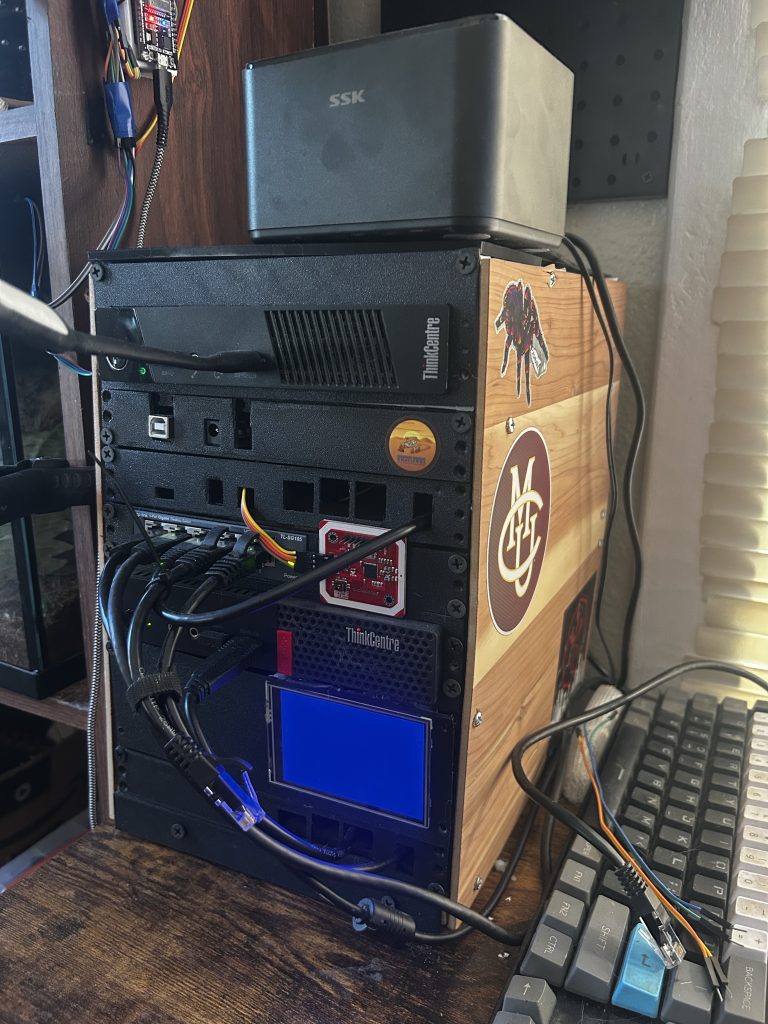
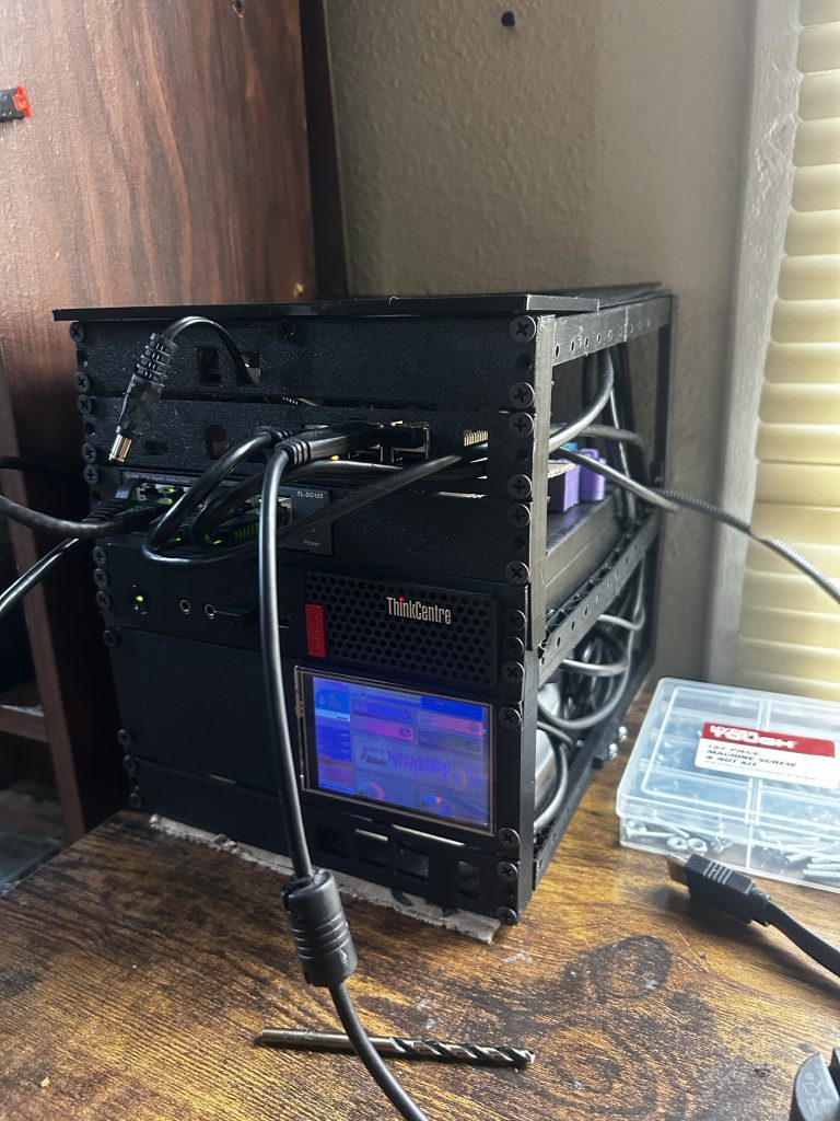
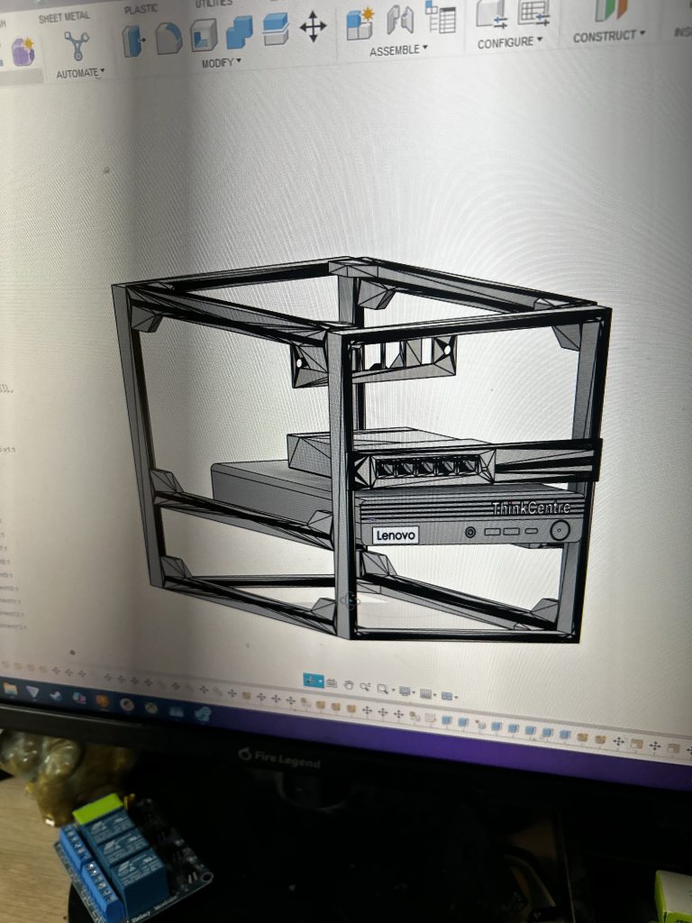
    To bring order (and a little flair) to my growing homelab, I went beyond software—I designed and 3D printed my own modular enclosure to house the key components of my server setup.

    What started as a project to mount a screen and a Raspberry Pi turned into a full-blown custom-built command station with support for:

    • 💻 Multiple Lenovo ThinkCentre units
    • 🧠 Raspberry Pi with built-in touchscreen support
    • 🏷️ NFC card reader/writer integration
    • 🔌 Clean cable management and modular power routing
    • 🌡️ Vents for airflow and cooling under server load

    🛠️ Design & CAD

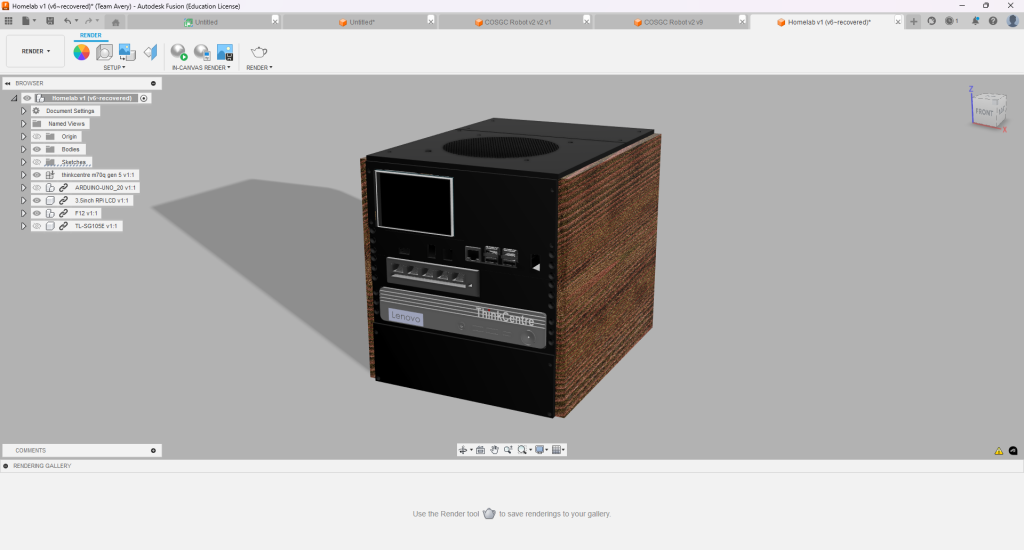
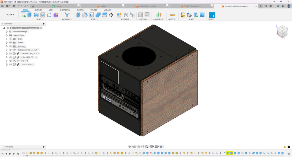
    I modeled the enclosure using Fusion 360, carefully planning space for:

    • Horizontal mounting slots for multiple ThinkCentre M-series SFF units
    • A secured Pi tray with access to GPIO headers
    • Cutouts for HDMI, USB, and Ethernet pass-through
    • Snap-in mounts for a 3.5″ TFT screen and camera module

    I included custom vents and fan brackets, using overlapping grill patterns to both diffuse airflow and add visual style.

    All parts were printed on my Ender 3 V2 using Pro Nylon for heat resistance near the Pi and ThinkCentre vents.


    📟 Integrated Screen Display

    On the front panel, I mounted a 3.5″ TFT Raspberry Pi display, which now runs a custom status screen showing:

    • CPU usage
    • Temperature
    • IP address
    • QR code for server access
    • NFC scan status when active

    This screen is powered by a lightweight Python app that refreshes live stats and supports soft shutdown/reboot buttons via GPIO.


    📶 NFC Access Control

    One of the most exciting additions is the NFC card reader/writer, mounted inside a flush front slot with LED feedback. I’ve programmed it to:

    • Read custom NFC tags for login or access triggers
    • Log tag scans to a local SQLite database
    • Eventually trigger services like user-specific dashboards or log retrieval

    (I’m exploring future use for secure local unlock of encrypted drives or launching custom user shells.)


    🔌 Multi-System Power & Clean Routing

    Cable routing is fully internal, using:

    • A fused DC power bus
    • Toggle switch for global shutdown
    • Mounting channels for SATA power routing and USB hub access

    🧩 Why I Built It

    This project was about blending hardware, CAD, software, and self-hosting into one physical artifact. It gave me full control over:

    • Layout and thermals
    • User interaction and expandability
    • Aesthetic and visual branding for my homelab

  • My Sound Experiments as httpsavery

    Beats, Loops, and Late Nights — How I Found Rhythm in Music Production

    Before I ever touched an oscilloscope or wrote a line of C++, I was layering samples and chopping snares. Under the alias httpsavery, I spent years producing original beats, mixes, and experimental loops—blending hip hop, lofi, and ambient influences into soundtracks for chill nights and creative flow.

    Music was my third creative pillar, alongside visual design and motion work. I composed everything from full beat tapes to curated playlists and SoundCloud radio-style mixes, teaching myself DAWs like FL Studio and Ableton Live along the way.

    🎚️ Skills That Carried Over

    Producing music gave me a deep respect for rhythm, iteration, and detail—skills I now use constantly in my engineering work:

    • Audio signal flow → wiring and circuits
    • DAW layering → multithreaded workflows
    • Loop-building → modular, testable design
    • Creative discipline → showing up and iterating daily

    What I Made:

    Instrumental Beats

    I crafted original instrumentals—some sampled, some completely from scratch—focusing on lofi textures, warm melodies, and hip-hop drum patterns.

    Tools used: FL Studio, Edison, RC-20, Gross Beat

    • Jazzy lofi tracks built on vinyl samples
    • Trap-inspired beats with custom 808s
    • Ambient pads and textured synth layering

    📻 httpsavery Radio

    I curated and blended my own tracks with others into chill mix tapes, complete with smooth transitions.

    Posted to SoundCloud as long-form listening experiences

    • Lofi road trip mixes
    • Ambient background sets for coding or drawing
    • Mood-based mixes (e.g. “fog”, “night walk”, “neon rain”)

    🎙️ Collabs & Custom Loops

    I also produced sample packs and loops for other small artists and remixers in the SoundCloud and Bandcamp community.

    Skills learned: EQ mixing, loop mastering, BPM/tempo matching

  • My Video Editing Origins

    Motion, Music, and Meaning — Learning Cinematics Through After Effects & Cinema 4D

    While my early graphic design work taught me visual composition, it was video editing that taught me motion and timing. Alongside my identity as Raven Arts, I created cinematic edits for gaming montages, channel intros, and community projects—mostly for the same online spaces I designed artwork for.

    Using Adobe After Effects and Cinema 4D, I taught myself how to sync motion with music, add kinetic typography, build custom 3D transitions, and render dramatic effects that elevated basic footage into stylized edits. These projects taught me not just software—but storytelling through movement.

  • My Early Graphic Design Journey

    From Logos to 3D Rendering: How Design Sparked My Creative Engineering Path

    Before I was wiring ECUs or designing robots, I was creating digital art under the name Raven Arts. As a teenager, I began freelancing online, designing custom artwork for a wide range of niche gaming communities—from fantasy MMOs to competitive FPS clans. I created everything from logos and social media banners to ad graphics and stream overlays, often working with content creators and guild leaders to bring their visions to life.

    Learning design early helped me get comfortable with complex creative software like Photoshop, Maya, Cinema 4D, Octane Renderer, and Fusion 360—tools I now use in much more technical contexts for engineering, animation, and 3D modeling.

    3D Renders

    Automotive Renders

    Logo Designs

    Banner Design